Amphibious vehicle

An amphibious, land-based technology, applied in amphibious vehicles, motor vehicles, transportation and packaging, etc., can solve the problems of low reliability, high cost, large air resistance, etc., and achieve high reliability, low resistance and low cost. Effect

Inactive Publication Date: 2011-05-25
周星果
View PDF0 Cites 12 Cited by
  • Summary
  • Abstract
  • Description
  • Claims
  • Application Information

AI Technical Summary

Problems solved by technology

[0002] At present, the amphibians adopt the following two technical schemes. The existing technical scheme 1: most of the amphibians use the buoyancy of the body in the water and propel them through the water The device travels in water and uses wheels or crawlers to travel on land. This technical solution is divided into two types for water travel and land travel. One is that the wheels or crawlers can be placed on the water surface through the retractable device, and the other is The wheels and tracks are not retractable, and they are always in the water when driving on water. The first type can only be used for light-loaded small vehicles because the wheels and tracks have various functions such as bearing the weight of vehicles, ships and loads, braking, and steering. Although the vehicle can run at a higher speed in water, the cost is high and the reliability is low; the second type is because the wheels or tracks are immersed in water, and the water resistance is extremely high at high speed. Although the cost is low, this type The speed of car or boat in water is extremely low, otherwise, just need to match very big motor, just because of above reason, the use of amphibian is greatly affected; Prior art scheme two: some amphibians are in Wheels or crawlers are used to drive on land, and movable or fixed special buoys or airbags are used to generate buoyancy in the water. Large air resistance affects the stability and aesthetics of the vehicle

Method used


Image

  • Amphibious vehicle
  • Amphibious vehicle
  • Amphibious vehicle

Examples


Embodiment Construction

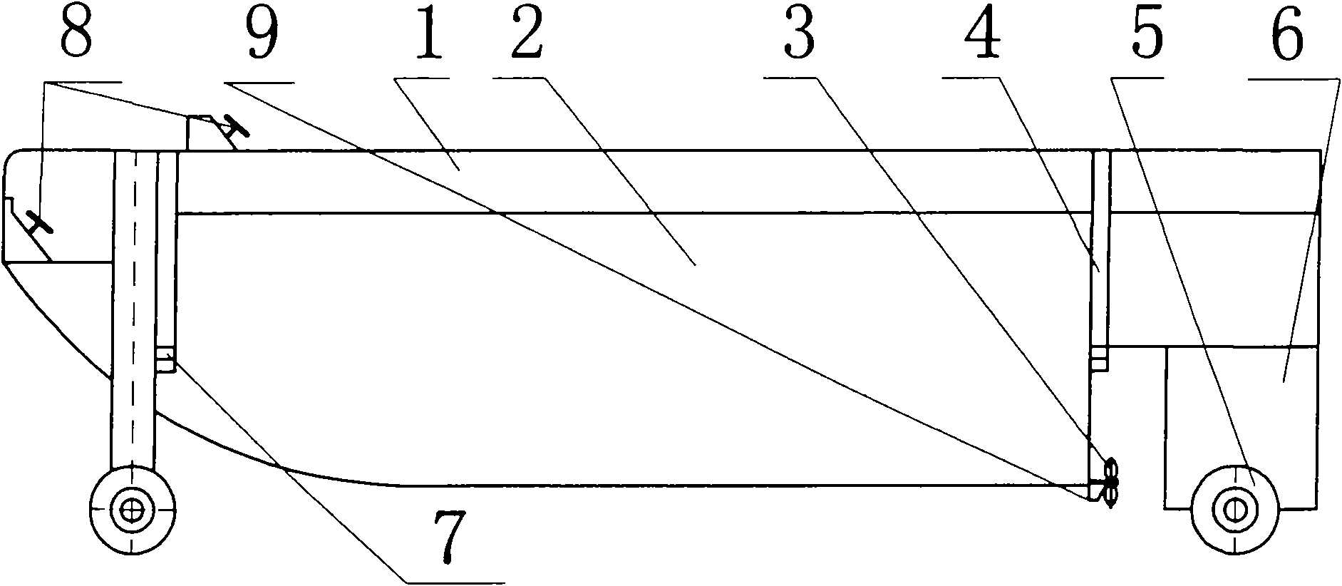
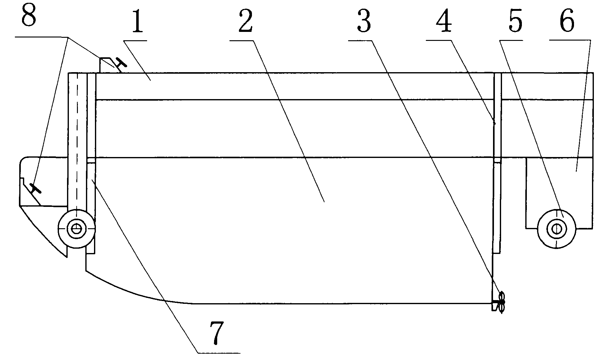
[0062] attached figure 1 and 2 Shown in is a wheeled amphibious boat with a rear engine compartment.

[0063] In this embodiment, the land travel device 5 is composed of four wheels, and the frame chassis 1 adopts a rear engine and a rear wheel drive mode; the clutch lifting device 4 is composed of a hydraulic cylinder, and one end of the piston of the hydraulic cylinder 4 is assembled in a boat-shaped The compartments 2 are connected, and one end of the cylinder barrel of the hydraulic cylinder 4 is assembled on the chassis frame 1; the water propulsion device 3 is a propeller, and the propeller is assembled on the boat-shaped compartment 2; 3 Driven by the power unit in the boat-shaped carriage 2, when on land, the boat-shaped carriage 2 receives the middle and upper part of the wheel 5 through the clutch lifting device 4, and the amphibian is driven by the wheel 5; when in water, the boat-shaped carriage 2 passes through The clutch lifting device 4 descends, and the boat-...


PUM


Abstract

The invention relates to an amphibious vehicle, which comprises a chassis frame, a boat-shaped carriage, a clutch lifting device, an on-land traveling device and a water scooter. The position change of the chassis frame and the boat-shaped carriage is controlled by the clutch lifting device. When on land, the boat-shaped carriage is positioned above the chassis frame or has a certain ground clearance, and the amphibious vehicle is driven on land by the chassis frame and the on-land traveling device. When in water, the boat-shaped carriage is descended by the clutch lifting device and produces a buoyancy force in the water, the chassis frame and the on-land traveling device are completely positioned on water, and the amphibious vehicle is driven in the water by the water scooter and the like. The boat-shaped carriage adopts a streamline boat shape, and resistance in the water is low, so the amphibious vehicle is driven in the water like a conventional boat. The on-land traveling device and the chassis frame are lifted together, and a braking device, a steering device, a suspension device and a transmission device required by travel on land all adopt part structures of a conventional vehicle, so the amphibious vehicle has low cost and high reliability.

Description

technical field [0001] The invention relates to an amphibious vehicle capable of running both on water and on land. technical background [0002] At present, the amphibians adopt the following two technical schemes. The existing technical scheme 1: Most of the amphibians use the buoyancy of the body in the water and drive in the water through the water propulsion device, and use wheels or crawlers to drive on land. The technical solution is to subdivide water driving and land driving into two types, one is that the wheels or crawlers can be placed on the water surface through the retractable device, and the other is that the wheels and crawlers are not retractable, and they are always in the water when driving on the water. In water, the first type can only be used for light-loaded small vehicles because the wheels and tracks have various functions such as bearing the weight of vehicles, ships and loads, braking, and steering. Although it can drive at a higher speed in water...

Claims


Application Information

Patent Timeline
Patent Type & Authority Applications(China)
IPC IPC(8): B60F3/00
CPCB60F3/00
Inventor 周星果
Owner 周星果
Why Eureka
Try Eureka