Method for detecting and assembling aircraft carbon brake discs
A technology of carbon brake discs and brake discs, which is applied in the field of detection and assembly of aircraft carbon brake discs, can solve problems such as gullies and unbalanced friction surface wear, and achieve the effects of improving service life, avoiding abnormal vibration, and reducing gully phenomena
- Summary
- Abstract
- Description
- Claims
- Application Information
AI Technical Summary
Problems solved by technology
Method used
Image
Examples
Embodiment 1
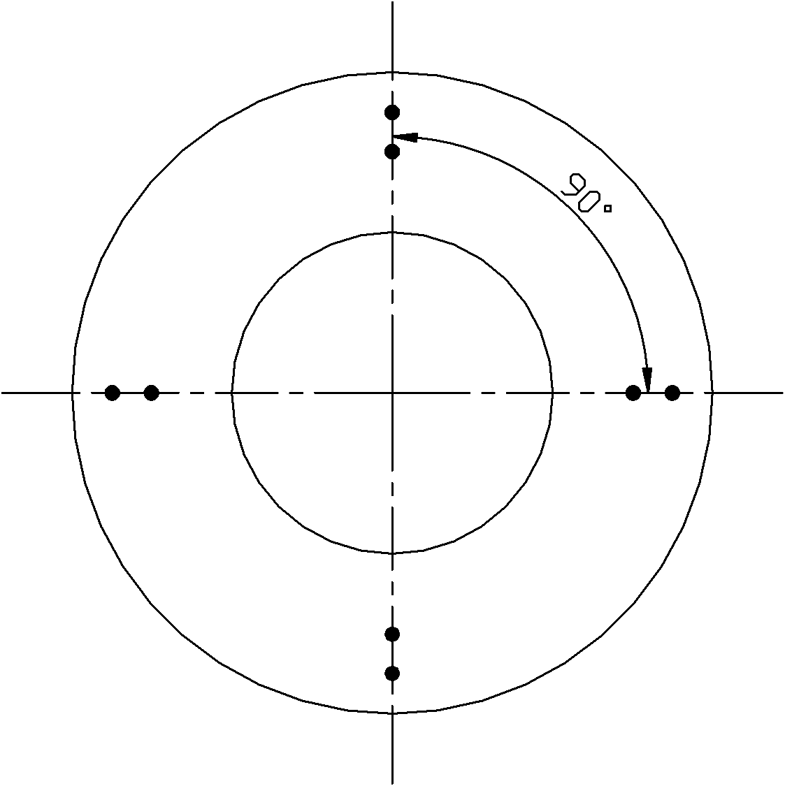
[0021] (1) Place the aircraft carbon brake disc horizontally, such as figure 1 Take 8 positions on the friction surface as shown in the figure as measurement points, and use a Shore hardness tester to measure the Shore hardness of the measurement points to obtain the Shore hardness values of the 8 measurement points;
[0022] (2) Discard the two values with the largest dispersion among the 8 Shore hardness values, and then calculate the arithmetic mean of the remaining Shore hardness values to obtain the average Shore hardness HS of the friction surface 1 ;
[0023] (3) Turn over the aircraft carbon brake disc, repeat steps (1) and (2) to obtain the average Shore hardness HS of another friction surface 2 ;
[0024] (4) Calculate HS 1 and HS 2 The arithmetic mean value of is used as the standard Shore hardness of aircraft carbon brake discs;
[0025] (5) Assemble the aircraft carbon brake discs with standard Shore hardness, and control the standard Shore hardness dif...
Embodiment 2
[0028] (1) Place the aircraft carbon brake disc horizontally, such as figure 1 Take 8 positions on the friction surface as shown in the figure as measurement points, and use a Shore hardness tester to measure the Shore hardness of the measurement points to obtain the Shore hardness values of the 8 measurement points;
[0029] (2) Discard the two values with the largest dispersion among the 8 Shore hardness values, and then calculate the arithmetic mean of the remaining Shore hardness values to obtain the average Shore hardness HS of the friction surface 1 ;
[0030] (3) Turn over the aircraft carbon brake disc, repeat steps (1) and (2) to obtain the average Shore hardness HS of another friction surface 2 ;
[0031] (4) Calculate HS 1 and HS 2 The arithmetic mean value of is used as the standard Shore hardness of aircraft carbon brake discs;
[0032] (5) Assemble the aircraft carbon brake discs with standard Shore hardness, and control the standard Shore hardness dif...
Embodiment 3
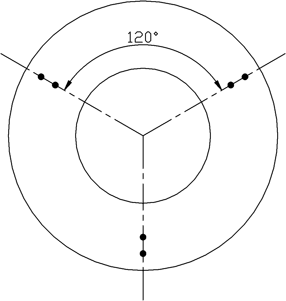
[0035] (1) Place the aircraft carbon brake disc horizontally, such as figure 2 As shown, take 6 positions on the friction surface as measurement points, and use a Shore hardness tester to measure the Shore hardness of the measurement points to obtain the Shore hardness values of the 6 measurement points;
[0036] (2) Discard the value with the largest dispersion among the 6 Shore hardness values, and then calculate the arithmetic mean of the remaining Shore hardness values to obtain the average Shore hardness HS of the friction surface 1 ;
[0037] (3) Turn over the aircraft carbon brake disc, repeat steps (1) and (2) to obtain the average Shore hardness HS of another friction surface 2 ;
[0038] (4) Calculate HS 1 and HS 2 The arithmetic mean value of is used as the standard Shore hardness of aircraft carbon brake discs;
[0039] (5) Assemble the aircraft carbon brake discs with standard Shore hardness, and control the standard Shore hardness difference between two...
PUM
 Abstract
Description
Claims
Application Information
 - R&D
- Intellectual Property
- Life Sciences
- Materials
- Tech Scout
- Unparalleled Data Quality
- Higher Quality Content
- 60% Fewer Hallucinations
Browse by: Latest US Patents, China's latest patents, Technical Efficacy Thesaurus, Application Domain, Technology Topic, Popular Technical Reports.
© 2025 PatSnap. All rights reserved.Legal|Privacy policy|Modern Slavery Act Transparency Statement|Sitemap|About US| Contact US: help@patsnap.com


