Inside and outside general bridge girder erection machine for high speed railway tunnel and girder erecting technology thereof

A technology for high-speed railways and bridge erection machines, which can be used in the erection/assembly of bridges, bridges, bridge construction, etc., and can solve problems such as difficulties

Active Publication Date: 2011-05-25
QINHUANGDAO TIANYE TOLIAN HEAVY INDUSTRY CO LTD +1
View PDF5 Cites 25 Cited by
  • Summary
  • Abstract
  • Description
  • Claims
  • Application Information

AI Technical Summary

Problems solved by technology

However, most of the existing bridge erecting machines are only suitable for erec...

Method used


Image

  • Inside and outside general bridge girder erection machine for high speed railway tunnel and girder erecting technology thereof
  • Inside and outside general bridge girder erection machine for high speed railway tunnel and girder erecting technology thereof
  • Inside and outside general bridge girder erection machine for high speed railway tunnel and girder erecting technology thereof

Examples


Embodiment Construction

[0055] The specific implementation of the present invention will be further described in conjunction with examples (with drawings):

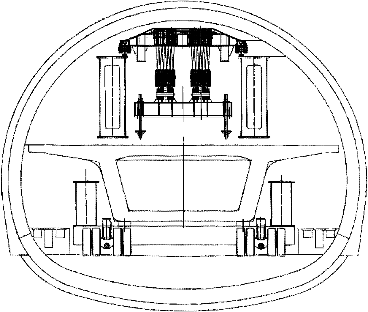
[0056] Such as figure 1 , figure 2 As shown, the present invention is composed of a rear outrigger 1, two flat beam cranes 2, a double main beam 3, a front outrigger 4, an auxiliary outrigger 5, and a concave tire-type beam carrier 6 (number in the figure) 7 means concrete beam to be erected).

[0057] by Figure 15 It can be seen that the foot of the two columns of the rear leg 1 is equipped with walking trolleys 1-4 to ride on the upper cover rails of the main beams 6-6 on both sides of the concave tire type beam transport vehicle 6. At the same time, the upper ends of the two uprights are connected to the corbels 3-2 on the rear side of the main beam through the front and rear pairs of horizontal pins 1-2. When the front horizontal pins 1-2 are pulled out, the rear outrigger 1 It can be folded back from the cylinder 1-3 (around the horizontal pi...


PUM


Abstract

The invention discloses an inside and outside general bridge girder erection machine for a high speed railway tunnel and a girder erecting technology thereof. Double girders (3) of the bridge girder erection machine are provided with two smooth hanging girder crown blocks (2); the front ends of double girders (3) are provided with front landing legs (4) and assistant landing legs (5); the tail parts of the double girders (3) are provided with rear landing legs (1) which can tilt and can support on the girders at two sides of a concave-volume tyre girder transportation car (6) after falling down; and the feet of the rear landing legs (1) are provided with travelling mechanisms which travel along the rails of the upper cover plates of girders (6-6) at two sides of the concave-volume tyre girder transportation car (6). The bridge girder erection machine feeds girders in a rear cantilever type, passes through holes in a front cantilever type, and transfers, packs and travels among bridges. The inside and outside general bridge girder erection machine can finish girder erection operation in and out of the high speed railway tunnel, can change the traditional bridge erection process into the simple bridge erection process, and has the advantages of high bridge girder erection efficiency, reliable safety performance and the like. Thus, the inside and outside general bridge girder erection machine solves the bottleneck problem for erecting prestressing force box-type concrete girders when the high speed railway is built in mountainous areas.

Description

Technical field [0001] The invention relates to a railway bridge erection equipment and a beam erecting process, in particular to a universal bridge erecting machine inside and outside high-speed railway tunnels and a beam erecting process. Background technique [0002] With the development of my country's high-speed railway construction, my country's high-speed railway has begun to enter the age of mountainous areas, such as the Great Southwest. To build high-speed railways in these areas is a tunnel through a bridge, which is connected by a bridge and tunnel, which is a must in the world. The objective situation is that there may be a bridge anywhere in the tunnel (across the karst cave section). Most of the existing bridge erecting machines are only suitable for erecting beams in plain areas. They cannot erect beams in the tunnel. Even the erection of beams at the entrance and exit of the tunnel and the passage through the tunnel are difficult and require very complicated dis...

Claims


Application Information

Patent Timeline
IPC IPC(8): E01D21/06
Inventor 黄耀怡王金祥郭欣李彬魏福祥张广谭王智勇覃艳明王旭
Owner QINHUANGDAO TIANYE TOLIAN HEAVY INDUSTRY CO LTD
Why Eureka
Try Eureka