Cyclone air-inlet centrifugal synchronous backward flow fan

A technology of air flow fan and air inlet, which is applied in the field of swirling air inlet and centrifugal synchronous backflow fan, which can solve the problems of unfavorable environmental protection, large eddy current loss, and large air inlet resistance, so as to improve the air inlet effect and increase the flow rate of the fan , the effect of saving energy

Inactive Publication Date: 2011-05-25
林钧浩
View PDF0 Cites 3 Cited by
  • Summary
  • Abstract
  • Description
  • Claims
  • Application Information

AI Technical Summary

Problems solved by technology

[0002] Now people use various centrifugal fans (mainly referring to general centrifugal backflow fans, centrifugal synchronous backflow fans, and centrifugal synchronous backflow ventilation compressors), the air inlet of the impeller changes from axial direction to radial direction suddenly, and the air inlet resistance is large. The eddy current loss is large, the air intake effect is poor, the efficiency is low, the noise is large, it consumes a lot of energy, and it is not conducive to environmental protection

Method used


Image

  • Cyclone air-inlet centrifugal synchronous backward flow fan
  • Cyclone air-inlet centrifugal synchronous backward flow fan
  • Cyclone air-inlet centrifugal synchronous backward flow fan

Examples


Embodiment 1

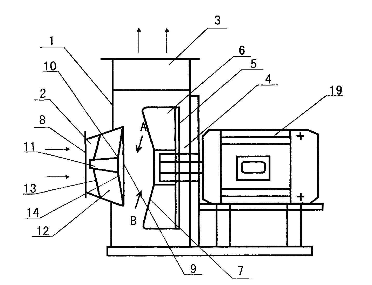
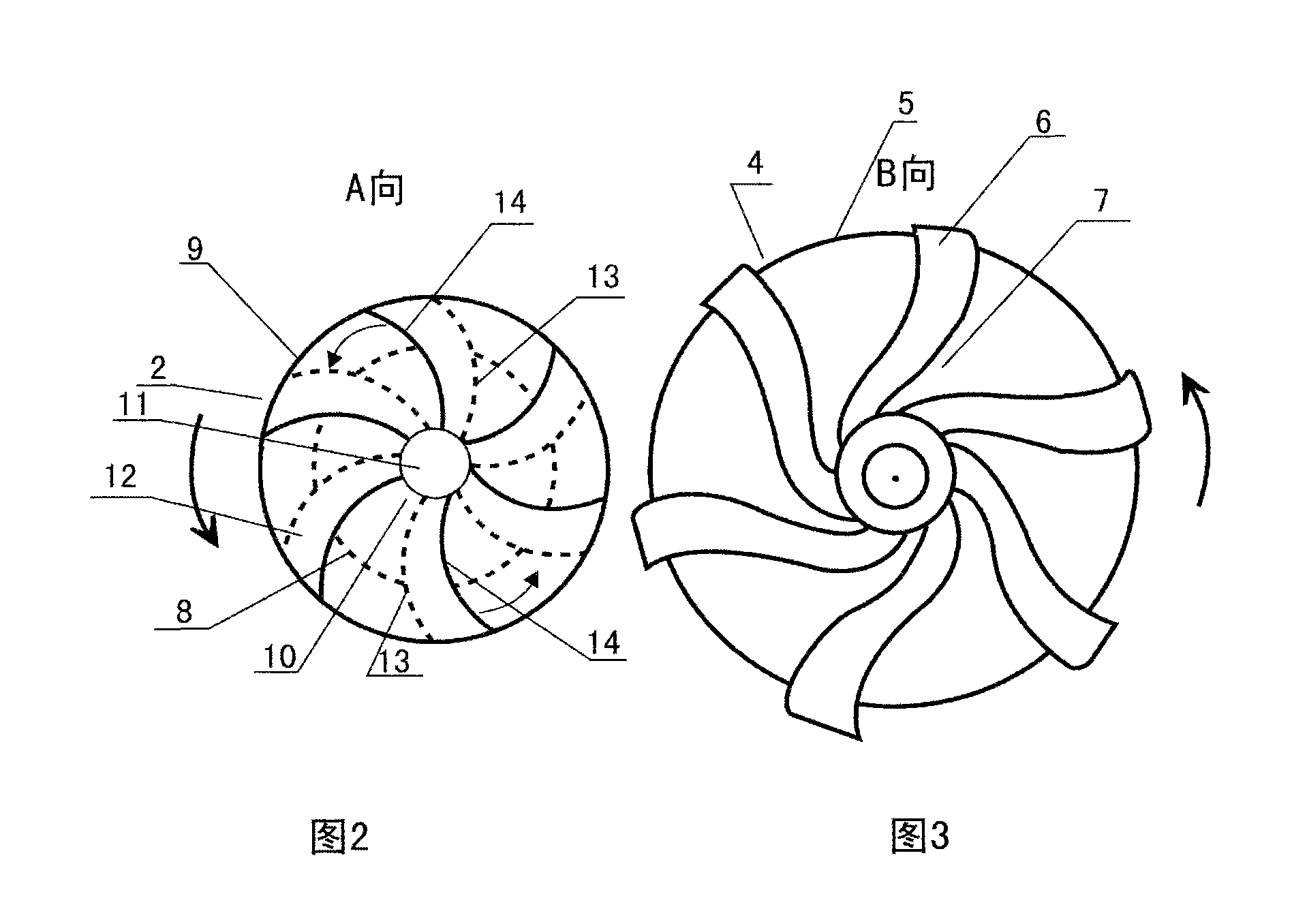
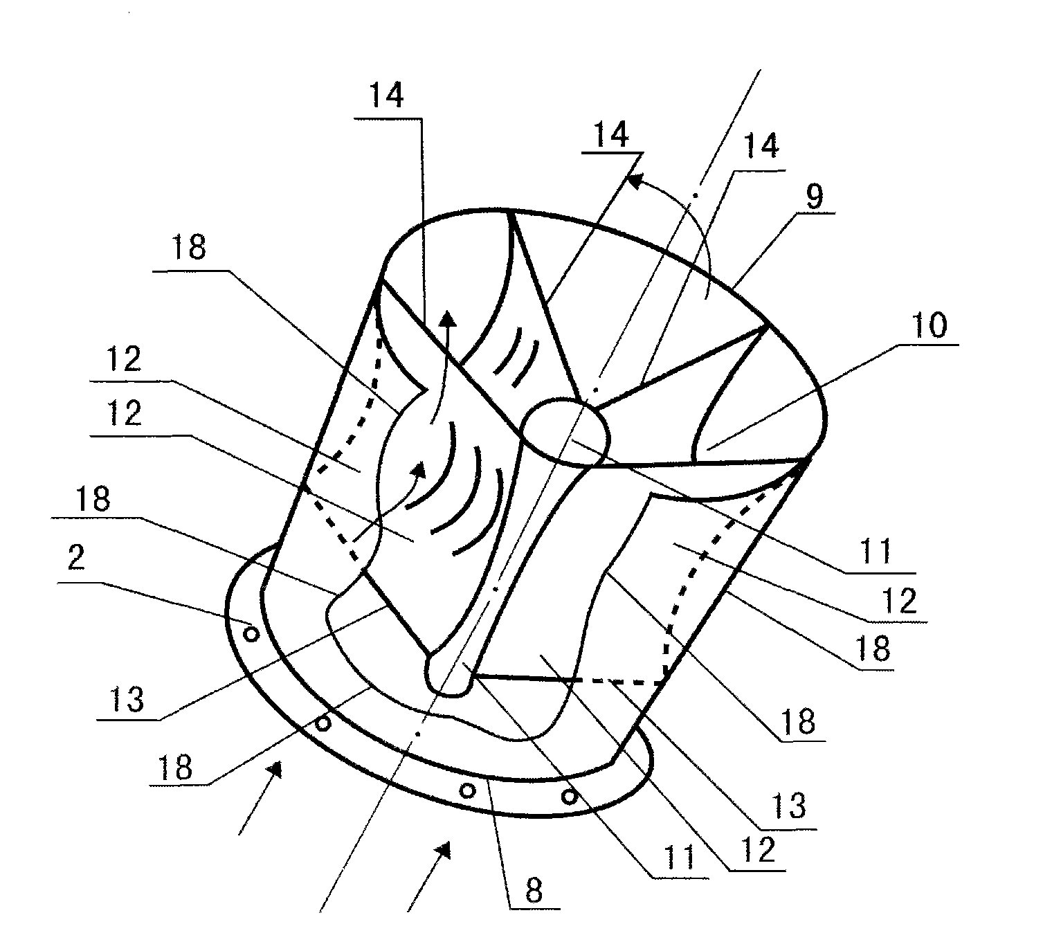
[0035] Embodiment 1, reference figure 1 , figure 2 , image 3 , Figure 4 , a centrifugal synchronous backflow fan with swirl air inlet, comprising a casing 1, an expanded casing air inlet 2, a casing air outlet 3, a backflow fan impeller 4, and a rear side impeller blade disc 5 (no front impeller blisk, no air inlet in the middle of the impeller), three-wall structure impeller blade 6, impeller blade axial inlet 7 (negative pressure gap), impeller air inlet inlet 8, casing air inlet outlet 9, casing air inlet 2 inside There is a swirl inducer 10. The swirl inducer 10 is composed of a conical cylindrical baffle connector 11 and a curved baffle blade 12. The baffle connector 11 runs longitudinally in the middle of the swirl inducer from front to back , the baffle blade 12 is a curved structure, the radial front end of the baffle blade 12 is connected with the baffle connector 11, the radial rear end of the baffle blade 12 is connected with the side wall of the air inlet 2 o...

Embodiment 2

[0041] Embodiment 2, refer to Figure 5 , Figure 6 , Figure 7 , This example is basically the same as Example 1, except that the impeller of this example is provided with an air inlet 15 in the middle of the impeller and a radial inlet 16 of the impeller blades, and the baffle connector is a cone-shaped structure.

[0042] When this example is working, the rotating airflow at the outlet of the air inlet of the casing will enter the inner flow channel of the impeller tangentially from two parts of the radial inlet 16 of the impeller blade and the axial inlet 7 of the impeller blade of the air inlet in the middle of the impeller, so that the impeller can be sucked in more. More air volume for processing.

[0043] This example is suitable for making various large-flow ventilators to use.

Embodiment 3

[0044] Embodiment 3, refer to Figure 8 , this example is basically the same as Example 2, the difference is that the impeller 4 of this example is a synchronous backflow ventilation compressor impeller, the whole impeller is a conical cylinder structure, the impeller blades are a synchronous backflow fan impeller blade structure, and the impeller blades are provided with There are synchronous diversion supercharger 17 and synchronous downstream inlet 7. The axial front side of the impeller is also provided with the air inlet 15 in the middle of the impeller, the radial (inclined) inlet 16 of the impeller blade is provided, and the axial inlet 7 of the impeller blade (synchronous downstream inlet) is provided. The baffle connector of the swirl flow inducer is in the form of a conical cylinder that expands from front to back.

[0045] When this example is working, the rotation direction of the airflow at the air inlet outlet 9 of the casing is opposite to that of the impeller,...


PUM


Abstract

The invention discloses a cyclone air-inlet centrifugal synchronous backward flow fan comprising a casing, an air inlet of the casing, an air outlet of the casing, an impeller, a vane disk of the impeller, a vane of the impeller, an axial inlet of the vane of the impeller, an inlet of the air inlet of the casing and an outlet of the air inlet of the casing. The cyclone air-inlet centrifugal synchronous backward flow fan is characterized in that a cyclone inducer is arranged in the air inlet of the casing and comprises a baffling connector and a baffling vane, the baffling connector penetrates through the middle of the cyclone inducer longitudinally along an axial direction from the front to the back, the baffling vane is in the form of a bending structure, the front end of the radial direction of the baffling vane is connected with the baffling connector, the back end of the radial direction of the baffling vane is connected with the side wall of the air inlet of the casing, an inlet of the baffling vane at the front end of the axial direction of the baffling vane points to the inlet of the air inlet of the casing along an axial direction, and an outlet of the baffling vane at the back end of the axial direction of the baffling vane points to the axial inlet of the vane of the impeller slantways along a circumferential direction. In the cyclone air-inlet centrifugal synchronous backward flow fan disclosed by the invention, a cyclone air-inlet principle is adopted, the air-inlet effect of the fan is greatly improved, the flow rate of the fan is increased, the total-pressure efficiency is enhanced, energy resources are saved, and noise is lowered.

Description

technical field [0001] The invention relates to a swirling air inlet centrifugal synchronous afterflow fan, which belongs to the field of gas machinery (the field of air purification machinery). Background technique [0002] Now people use various centrifugal fans (mainly referring to general centrifugal backflow fans, centrifugal synchronous backflow fans, and centrifugal synchronous backflow ventilation compressors), the air inlet of the impeller changes from axial direction to radial direction suddenly, and the air inlet resistance is large. The eddy current loss is large, the air intake effect is poor, the efficiency is low, and the noise is large, which consumes a lot of energy and is not conducive to environmental protection. Contents of the invention [0003] The purpose of the present invention is to overcome the above-mentioned shortcoming of the prior art, and provide a kind of directly change the axial linear airflow of blower air inlet into the rotating airflow...

Claims


Application Information

Patent Timeline
Patent Type & Authority Applications(China)
IPC IPC(8): F04D17/08F04D29/44F04D29/28
Inventor 林钧浩
Owner 林钧浩
Why Eureka
Try Eureka