
Hydraulic coupler

A technology of hydraulic couplings and jackets, applied in couplings, rigid shaft couplings, mechanical equipment, etc., can solve problems such as pulling or even seizure, low friction coefficient and power transmission capacity, and scrapped couplings.

Inactive Publication Date: 2011-05-25
无锡鸿海龙船机有限公司
View PDF4 Cites 3 Cited by
  • Summary
  • Abstract
  • Description
  • Claims
  • Application Information

AI Technical Summary

Problems solved by technology

[0007] Practice has proved that the couplings of the above forms have the following disadvantages: since the friction surfaces of the inner and outer sleeves do not undergo any surface treatment, it is easy to cause roughening or even seizure during high-pressure friction, resulting in the scrapping of the inner, outer, and even the entire coupling
The friction coefficient and power transmission capacity of the above structure products are low

Method used


Image

  • Hydraulic coupler
  • Hydraulic coupler
  • Hydraulic coupler

Examples


Embodiment 1

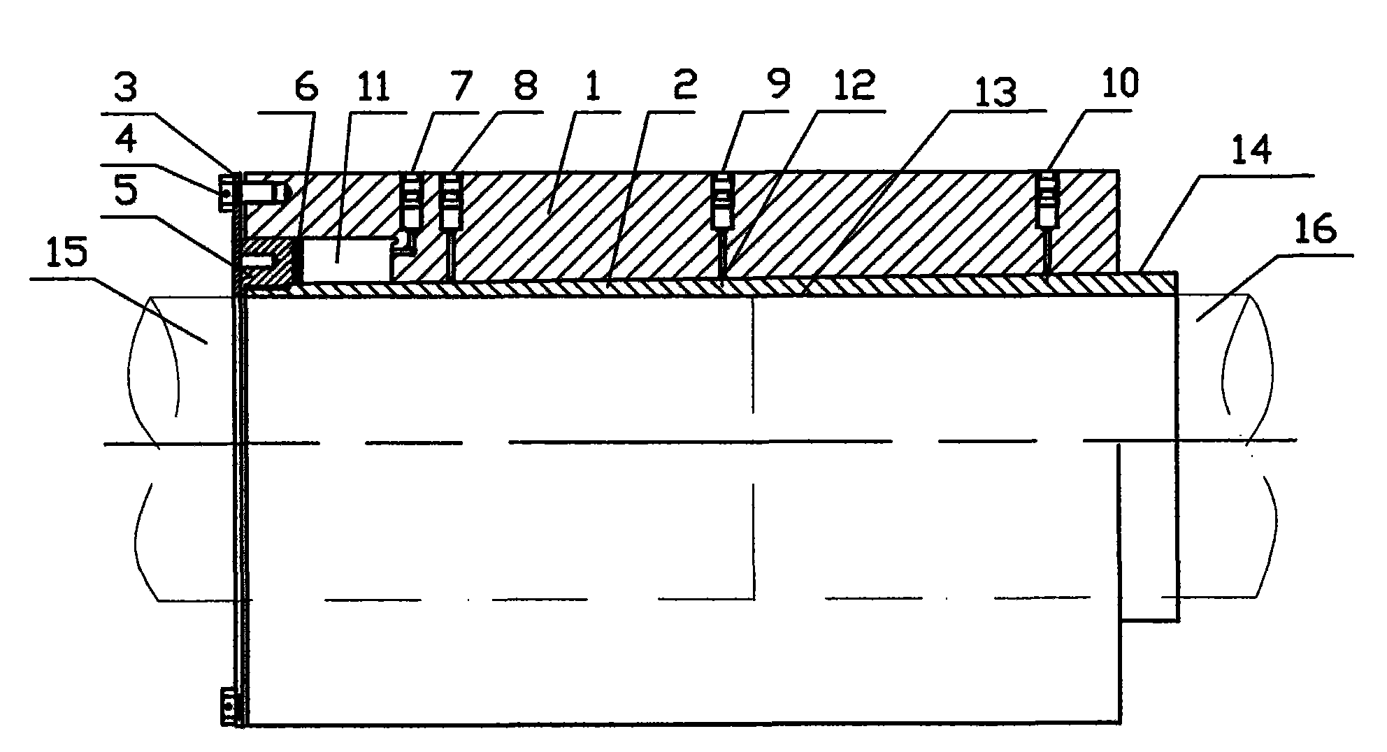
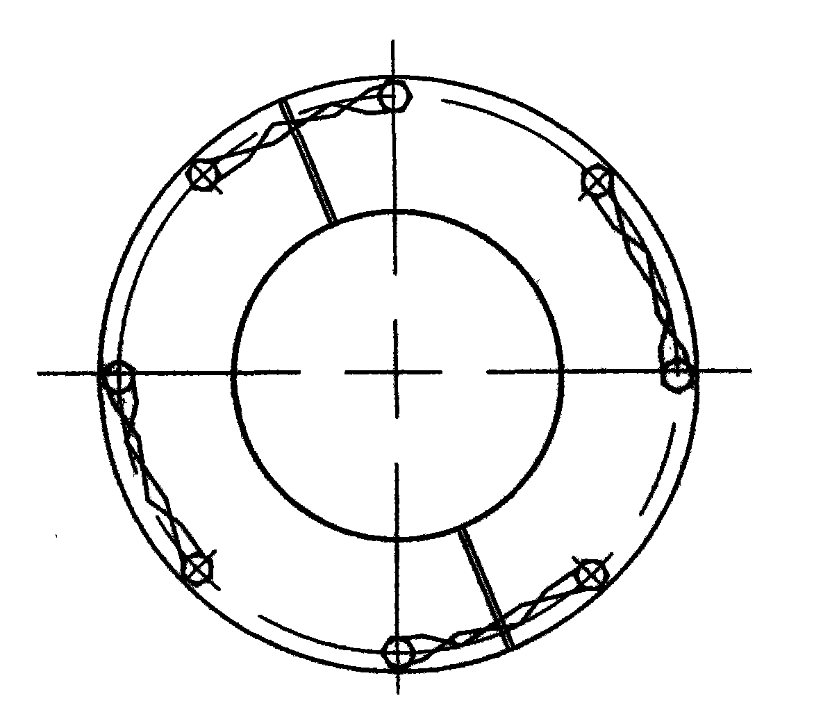
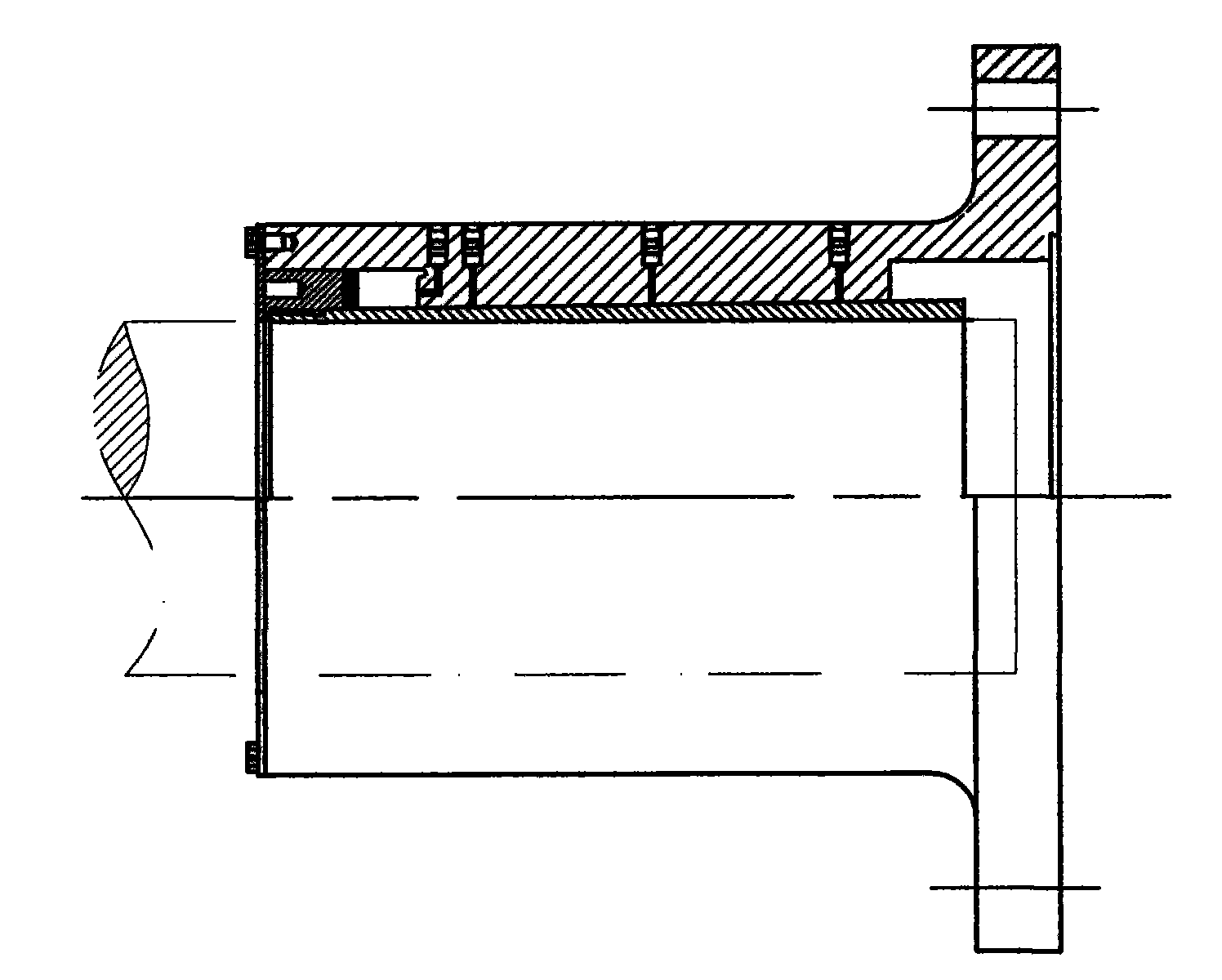
[0021] Such as figure 1 , figure 2 Shown, sleeve-type hydraulic couplings, including:

[0022] Jacket: the inner surface 12 is conical, the outer surface is cylindrical, and has a spiral oil groove; one end is processed into a step shape, which is used as the piston area 11 to push the outer jacket to move axially; there are several oil injection holes on the outer jacket, one of which is It is used to inject oil into the piston area 11 to generate axial displacement, and the rest communicates with the oil groove on the inner surface 12 of the casing for radial expansion.

[0023] Inner sleeve: its inner surface 13 is cylindrical, and there are several helical grooves for oil storage, and the outer surface 14 is conical; one end of the inner sleeve is processed into threads for connecting with the piston.

[0024] Piston 5: its inner hole is threaded and connected with the inner sleeve, and a sealing ring 6 is provided.

[0025] The outer sleeve, the inner sleeve and the e...


PUM


Abstract

A hydraulic coupler comprises an inner jacket and an outer jacket connected in a matching manner from inside to outside; the outer surface of the inner jacket and the inner surface of the outer jacket are conical; and the outer surface of the inner jacket is a nitrocarburizing treatment surface and is divided into three layers which are an alloy nitride-carbon compound layer, a dispersing layer and a matrix layer in turn from top to bottom. The nitrocarburizing treatment for the inner jacket of the hydraulic coupler is carried out to realize carbonitriding so as to change the surface property. The dry frictional factor of the hydraulic coupler can reach 0.4-0.65, and the hydraulic coupler has high rodent resistance, scratch resistance, fatigue resistance and corrosion resistance.

Description

technical field [0001] The invention relates to a shaft coupling, in particular to a keyless hydraulic coupling. Background technique [0002] At present, the general structure of the domestically produced keyless hydraulic couplings for coupling between shafts is as follows: [0003] Jacket: the inner surface is conical, the outer surface is cylindrical, and has a spiral oil groove; one end is processed into a step shape, which is used as a piston area to push the outer casing to move axially; there are several oil injection holes on the outer jacket, one of which is used for Oil injection to the piston area produces axial displacement, and the rest communicates with the oil groove on the inner surface of the casing for radial expansion. There is also a hydraulic coupling with an outer jacket and an inner jacket, which is called a double-layer prestressed structure. [0004] Inner sleeve: Its inner surface is cylindrical, and there are several helical grooves for oil stor...

Claims


Application Information

Patent Timeline
IPC IPC(8): F16D1/091C23C8/26
Inventor 张英
Owner 无锡鸿海龙船机有限公司
Learn More