Vacuum toilet dejecta collector gate valve

A gate valve and vacuum collection technology, which is applied in the field of the collection system of passenger transportation vehicles, can solve the problems of high failure rate, high air leakage and failure rate, and poor sealing performance of imported butterfly valves and slide valves, so as to reduce the application of The effect of cost, reasonable structure and simple structure

Pending Publication Date: 2019-01-29
QINGDAO GEWUZHENGFANG ELECTROMECHANICAL TECH CO LTD
View PDF0 Cites 2 Cited by
  • Summary
  • Abstract
  • Description
  • Claims
  • Application Information

AI Technical Summary

Problems solved by technology

[0005] Aiming at the problems of air leakage and high failure rate of the butterfly valve and slide valve on the channel from the urinal to the dirt tank, the present invention proposes a new scheme of reconsidering the transmission mechanism of the gate valve and changing the structure of the seal to improve the imported butterfly valve And slide valve failure rate is high, poor sealing performance and large operating resistance; the valve structure is simple, in line with the general laws of mechanical design, designed a hollow sealing ring and put forward the concept of sealing pressure self-adaptation; this is very important for stable gate valve performance , It is of great significance to reduce the failure rate and reduce the cost

Method used


Image

  • Vacuum toilet dejecta collector gate valve
  • Vacuum toilet dejecta collector gate valve
  • Vacuum toilet dejecta collector gate valve

Examples


Embodiment Construction

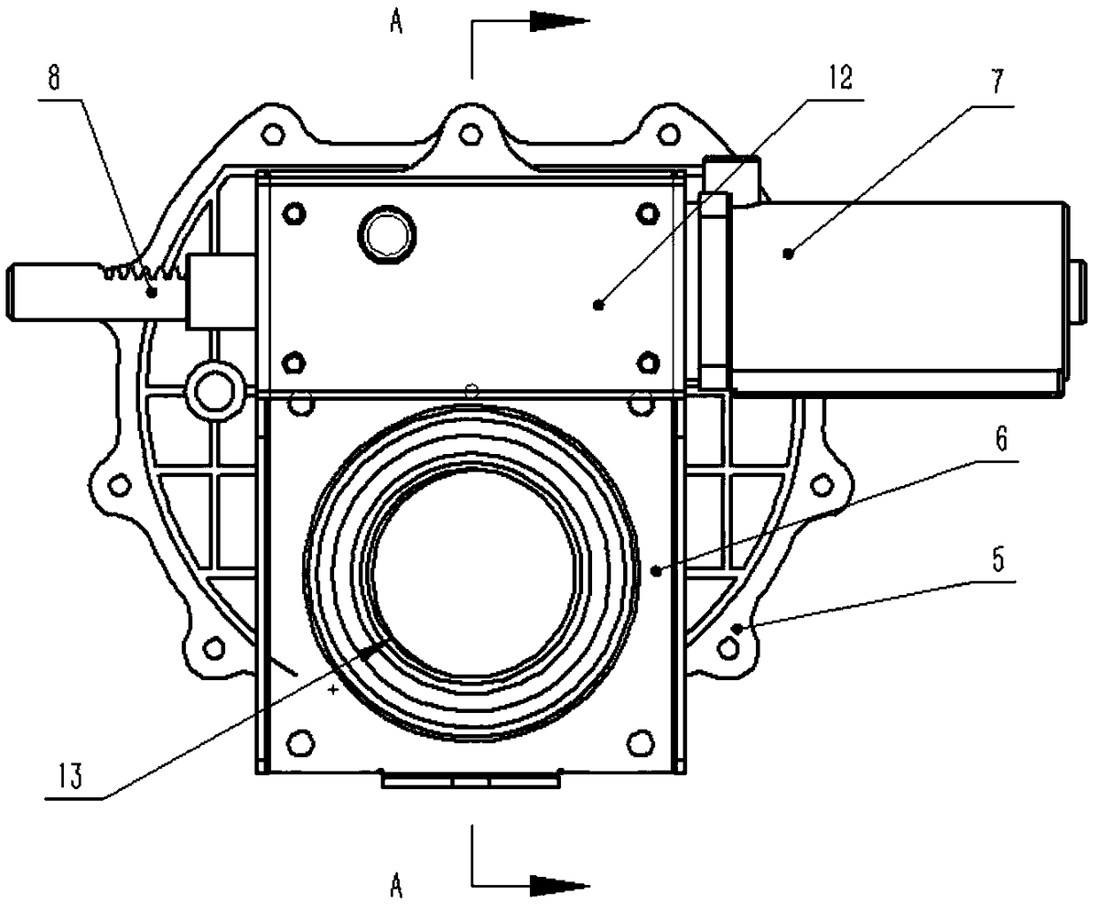
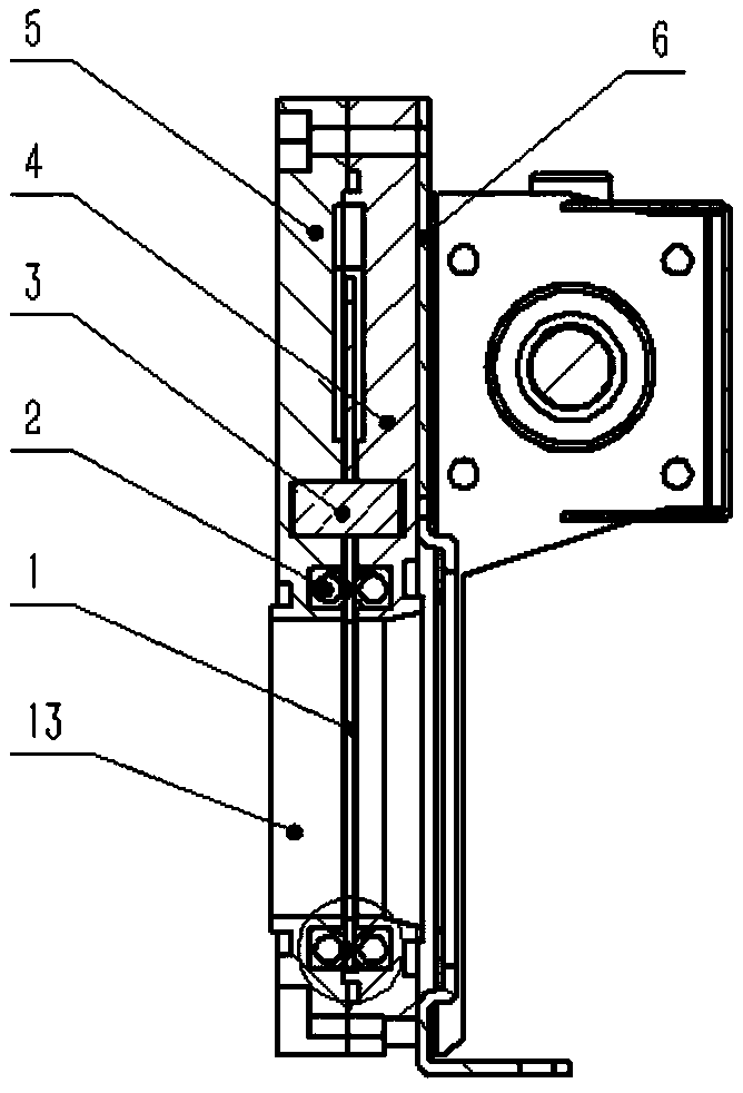
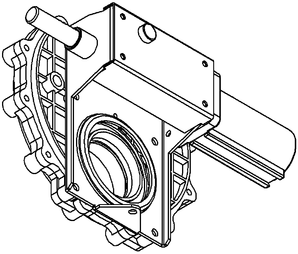
[0026] The structure of each part of the gate valve of the vacuum type lavatory pan of the present invention is as follows: Figure 1-7 shown.

[0027] In order to be applicable to the structure of the existing vacuum feces collection system, the upper splint 4 and the lower splint 5 are designed in a crescent shape.

[0028] The gate plate 1 and the gear of the vacuum toilet gate valve are as follows: Figure 6 As shown, the modulus of the gear is 1, and the number of complete gear teeth is 60. Here, only a part of the gear is required, see 102; 101 is the gear shaft hole, which is also the central shaft hole of the gate 1, which can be pushed under the action of the driving gear. The gate 1 rotates; the gate valve opens when the sewage hole 103 on the gate 1 coincides with the sewage hole of the upper and lower splints. The diameter of the hole 103 is 46mm;

[0029] The hollow sealing ring 2 of the gate valve of the vacuum-type toilet collection is open in the natural sta...


PUM


Abstract

The invention discloses a vacuum toilet dejecta collector gate valve which comprises an upper clamping plate, a lower clamping plate, a gate, an air cylinder, a driven gear and a driving gear. The upper clamping plate and the lower clamping plate are mutually buckled, the gate is located between the upper clamping plate and the lower clamping plate, and the driven gear and the driving gear are installed at the two ends of a gear shaft correspondingly. The gate comprises an opening area, a blocking and a driving area which are distributed in the shape like the Chinese character 'pin'. Annular grooves are formed in the peripheries of dejecta through holes of the upper clamping plate and the lower clamping plate, hollow sealing rings are embedded in the annular grooves, the front portion of apiston rod of the air cylinder is provided with a rack to be engaged with driving teeth, the rack is driven by the air cylinder, the gate valve is opened when the dejecta through holes of the upper and lower clamping plates coincide with a through hole in the gate, and the gate valve is closed when the dejecta through holes in the upper and lower clamping plates coincide with the blocking area onthe gate. A self-adaptive O-shaped ring is designed, and positive pressure of the O-shaped ring to the gate is changed along with changes of pressure of a pressure cavity within a certain range. Thestructure is reasonable, performance is reliable, therefore, the maintenance workload of a high speed rail dejecta collection system can be reduced, and the application cost is reduced.

Description

technical field [0001] The invention relates to a gate valve for a vacuum toilet collection device, which is used to control the switch of the sewage discharge channel of the vacuum toilet collection system on equipment such as aircraft, high-speed rail, and road passenger vehicles, and belongs to the technical field of toilet collection systems for passenger vehicles. Background technique [0002] The valves required for the dirt passage of the vacuum defecation collection system are different from the general valves of the general defecation collection system, and have higher requirements for the reliability and durability of the valves. Taking the high-speed rail as an example, once there is a problem with the toilet collection system of the high-speed rail, the toilet must be shut down immediately, which will not only affect the use of passengers, but also cause serious damage to the riding environment, and the valve plays an extremely important role in the system; Altho...

Claims


Application Information

Patent Timeline
Patent Type & Authority Applications(China)
IPC IPC(8): F16K3/06F16K3/314F16K31/122F16K31/54E03D5/00E03D9/16
CPCE03D5/00E03D9/16F16K3/0227F16K3/0254F16K3/06F16K3/314F16K31/122F16K31/54
Inventor 何西荣柴福记李雪萍朱明华姜军
Owner QINGDAO GEWUZHENGFANG ELECTROMECHANICAL TECH CO LTD
Why Eureka
Try Eureka