Hydraulic support push rod
A hydraulic support and push rod technology, applied in the direction of rigid pipes, slender components, pipes, etc., can solve the problems of low safety factor, short service life, and difficulty in using the internal space of push rods, etc., to achieve extended service life, function expansion, Easy to apply promoted effects
- Summary
- Abstract
- Description
- Claims
- Application Information
AI Technical Summary
Problems solved by technology
Method used
Image


Examples
Embodiment Construction
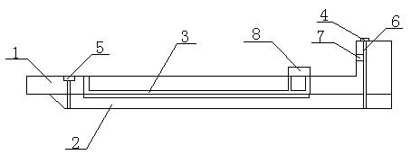
[0012] like figure 1 It is a structural schematic diagram of the present invention. The hydraulic support push rod includes a rod body upper part 1, a rod body lower part 2, a groove 3 and a fixing block 4. The rod body upper part 1 and the rod body lower part 2 are fixedly connected, and the rod body upper part 1 and the rod body lower part 2 are provided with a concave Groove 3, the upper right side of the upper part of the rod body 1 is provided with a fixed block 4, the upper part of the rod body 1 and the lower part of the rod body 2 are fixedly connected by screws 5 and fixing pins 6, the right side of the upper part of the rod body 1 is provided with a sticker 7, and the upper part of the rod body 1 is provided with There are quick connectors 8.
[0013] During use, the upper right side of the upper body of the rod 1 is provided with a fixed block 4, and the fixed block 4 is provided with a pin hole. The head of the lower part 2 of the rod body is fixedly connected by ...
PUM
 Abstract
Description
Claims
Application Information
 - Generate Ideas
- Intellectual Property
- Life Sciences
- Materials
- Tech Scout
- Unparalleled Data Quality
- Higher Quality Content
- 60% Fewer Hallucinations
Browse by: Latest US Patents, China's latest patents, Technical Efficacy Thesaurus, Application Domain, Technology Topic, Popular Technical Reports.
© 2025 PatSnap. All rights reserved.Legal|Privacy policy|Modern Slavery Act Transparency Statement|Sitemap|About US| Contact US: help@patsnap.com