Experimental device for simulating 200-meter deep water blasting under moving water state

An experimental device and state-of-the-art technology, applied in blasting and other directions, can solve problems such as low similarity, complex and difficult underwater blasting research, and achieve a reasonable design effect

Inactive Publication Date: 2011-05-25
WUHAN UNIV OF SCI & TECH
View PDF3 Cites 17 Cited by
  • Summary
  • Abstract
  • Description
  • Claims
  • Application Information

AI Technical Summary

Problems solved by technology

Underwater blasting also includes many uncertain factors, such as the type of explosive in underwater blasting, the size of the charge, the distance from the explosive to the structure, the underwater environment, etc. All of the above characteristics make the research on underwater blasting quite complicated and difficult. difficulty
[0004] For this reason, the research

Method used


Image

  • Experimental device for simulating 200-meter deep water blasting under moving water state
  • Experimental device for simulating 200-meter deep water blasting under moving water state

Examples


Embodiment 1

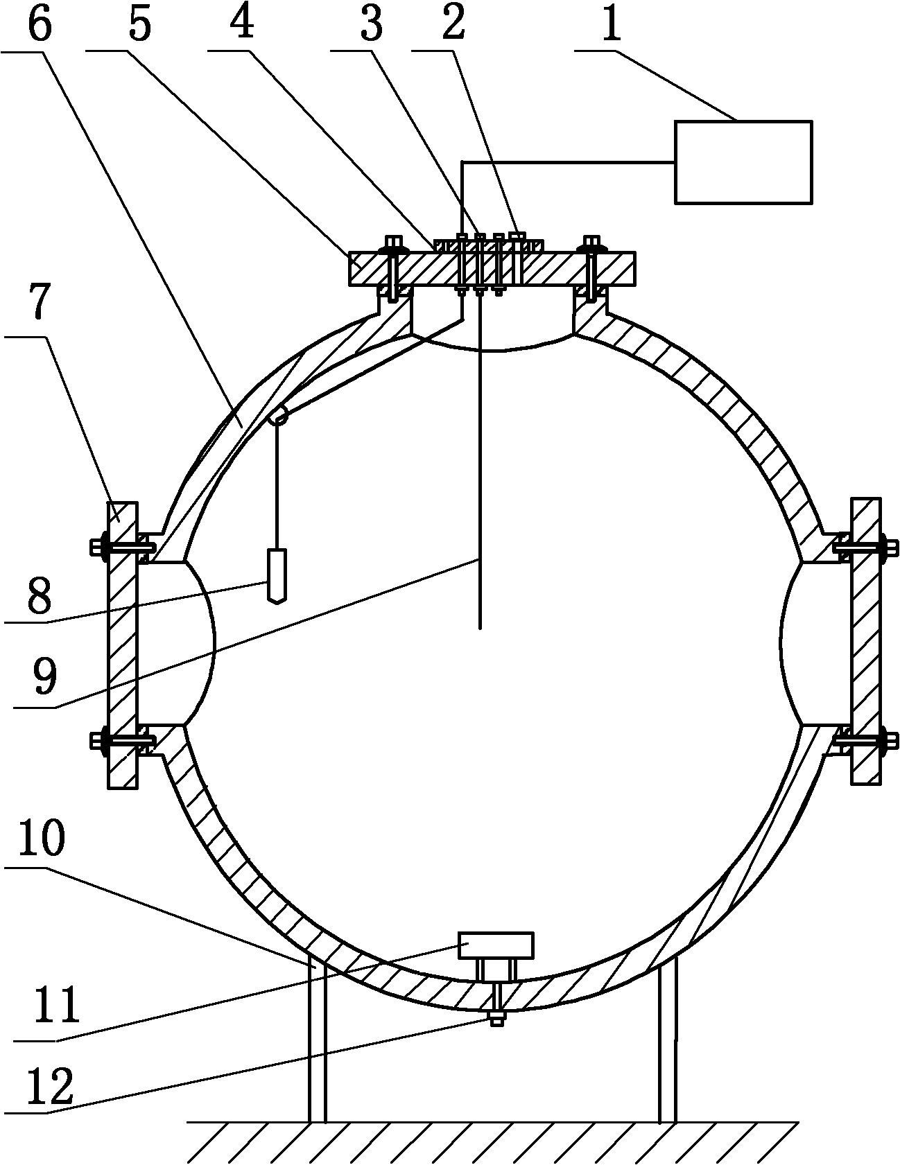
[0017] A 200-meter-level deep-water blasting experimental device under simulated dynamic water state. Such as figure 1 As shown: the device is a hollow spherical tank 6 made of A3 steel, with an inner diameter of 1500-2000 mm and a wall thickness of 5-10 mm; the bottom of the hollow spherical tank is fixed on the base support 10 .

[0018] The tank body of the hollow spherical tank 6 is symmetrically provided with two observation windows 7, and the center line of the two observation windows 7 passes through the center of the tank body 6. The diameters of the observation windows 7 are both 200-300mm, and the observation windows 7 are Equipped with plexiglass.

[0019] The top of the hollow spherical tank 6 has a working hole, and the working hole is equipped with a mounting cover 5. The mounting cover 5 is provided with three penetration holes 3 with a diameter of 5-7mm and a high-pressure air pipe joint 2. Three penetration holes 3 and the high-pressure air pipe joint 2 are ...

Embodiment 2

[0023] A 200-meter-level deep-water blasting experimental device under simulated dynamic water state. Such as figure 1 As shown: the device is a hollow spherical tank 6 made of A3 steel, with an inner diameter of 2000-2500 mm and a wall thickness of 10-15 mm; the bottom of the hollow spherical tank is fixed on the base support 10 .

[0024] The tank body of the hollow spherical tank 6 is symmetrically provided with two observation windows 7, and the center line of the two observation windows 7 passes through the center of the tank body 6. The diameters of the observation windows 7 are all 300-400 mm, and the observation windows 7 are Equipped with plexiglass.

[0025] The top of the hollow spherical tank 6 is provided with a working hole, and the working hole is equipped with an installation cover 5, and the installation cover 5 is provided with three penetration holes 3 with a diameter of 6-8mm and a high-pressure air pipe joint 2, the penetration hole 3 and the high-pressur...


PUM

PropertyMeasurementUnit
The inside diameter ofaaaaaaaaaa
Wall thicknessaaaaaaaaaa
Thicknessaaaaaaaaaa

Abstract

The invention relates to an experimental device for simulating 200-meter deep water blasting under the moving water state. The technical scheme is that: the device is a hollow spherical tank (6); two observation windows (7) are symmetrically formed on the tank body of the hollow spherical tank (6) and are provided with organic glass; a working hole on the top of the hollow spherical tank (6) is provided with an installation cover (5) which is provided with three penetration holes (3) and a high pressure air pipe joint (2); the bottom of the hollow spherical tank (6) is provided with a water pipe joint (12); a lead (9) connected with explosive passes through one of the three penetration holes (3); a waterproof shielding cable connected with a pressure sensor (8) passes through another hole of the three penetration holes (3), and is connected with a data acquisition instrument (1); an electric stirrer (11) is arranged on the inner wall of the bottom of the hollow spherical tank (6); and a wire connected with the electric stirrer (11) passes through the third hole of the three penetration holes (3) and is externally connected with a power control device. The device has the characteristics of reasonable design, convenience of manufacture, and high similarity to actual environment.

Description

technical field [0001] The invention belongs to the technical field of blasting quasi-experimental devices. In particular, it relates to a 200-meter-level deep-water blasting experimental device under simulated dynamic water state. Background technique [0002] With the development of blasting technology, underwater engineering blasting is more and more widely used in blasting reefs, dredging channels, excavating foundation pits of hydraulic structures, excavating canals, underwater pipelines, underwater blasting and compacting, and deep-sea mining of petroleum engineering. Explosive demolition of post-waste, etc. [0003] Underwater engineering blasting refers to the process of extremely large energy conversion in a limited underwater volume in a very short time. Underwater blasting can be roughly divided into three stages: detonation of explosives, generation and propagation of shock waves, formation and pulsation of bubbles. The output energy of explosives in underwate...

Claims


Application Information

Patent Timeline
IPC IPC(8): F42D1/00
Inventor 钟冬望陈浩余刚
Owner WUHAN UNIV OF SCI & TECH
Why Eureka
Try Eureka