
Connection testing device of electric energy metering device and using method thereof

A technology of electric energy metering device and testing device, which is applied in the direction of measuring device, measuring electric variable, measuring electricity, etc., which can solve problems such as errors, inconvenient, heavy carrying weight, etc.

Active Publication Date: 2011-05-25
JIANGSU ELECTRIC POWER CO +1
View PDF5 Cites 20 Cited by
  • Summary
  • Abstract
  • Description
  • Claims
  • Application Information

AI Technical Summary

Problems solved by technology

[0002] In the measurement process of electric energy metering devices (such as electric energy meters), at present, the meter installation and wiring personnel can only use a multimeter to roughly test whether the wiring of the electric energy meter is connected before the power metering cabinet is closed and the power supply is not available on site. Correct, sometimes you have to remove the stitches to check. This method is inconvenient and inaccurate, and it is easy to cause human errors
In the existing technology, there are mainly four problems: no external power supply on site, heavy weight for easy portability, efficiency improvement to achieve energy saving, whether the inspected equipment has a high-voltage transformer, voltage and current setting and detection

Method used

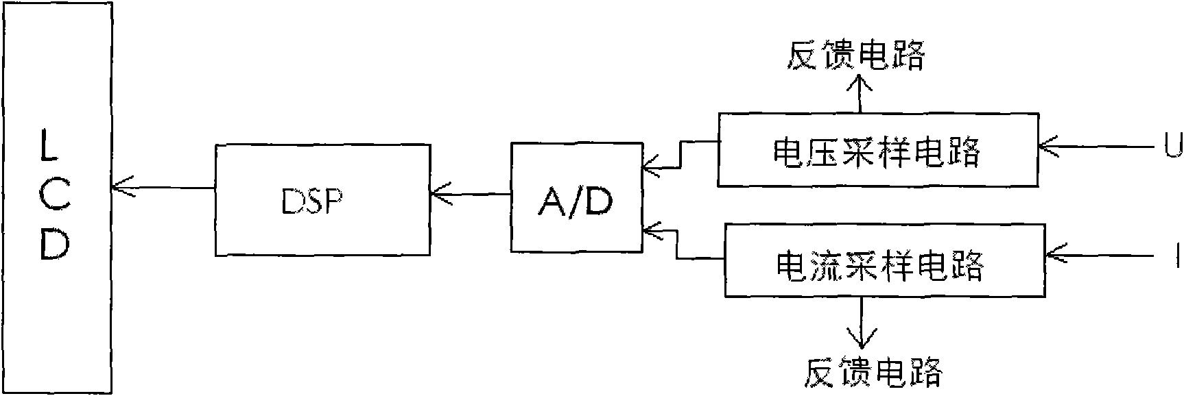

Image

  • Connection testing device of electric energy metering device and using method thereof
  • Connection testing device of electric energy metering device and using method thereof
  • Connection testing device of electric energy metering device and using method thereof

Examples


Embodiment Construction

[0021] The present invention will be further described below in conjunction with the accompanying drawings and specific embodiments.

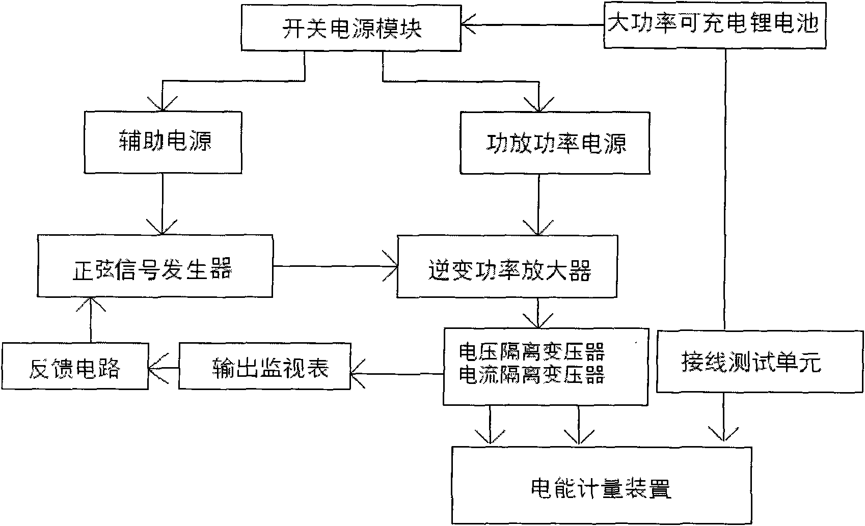
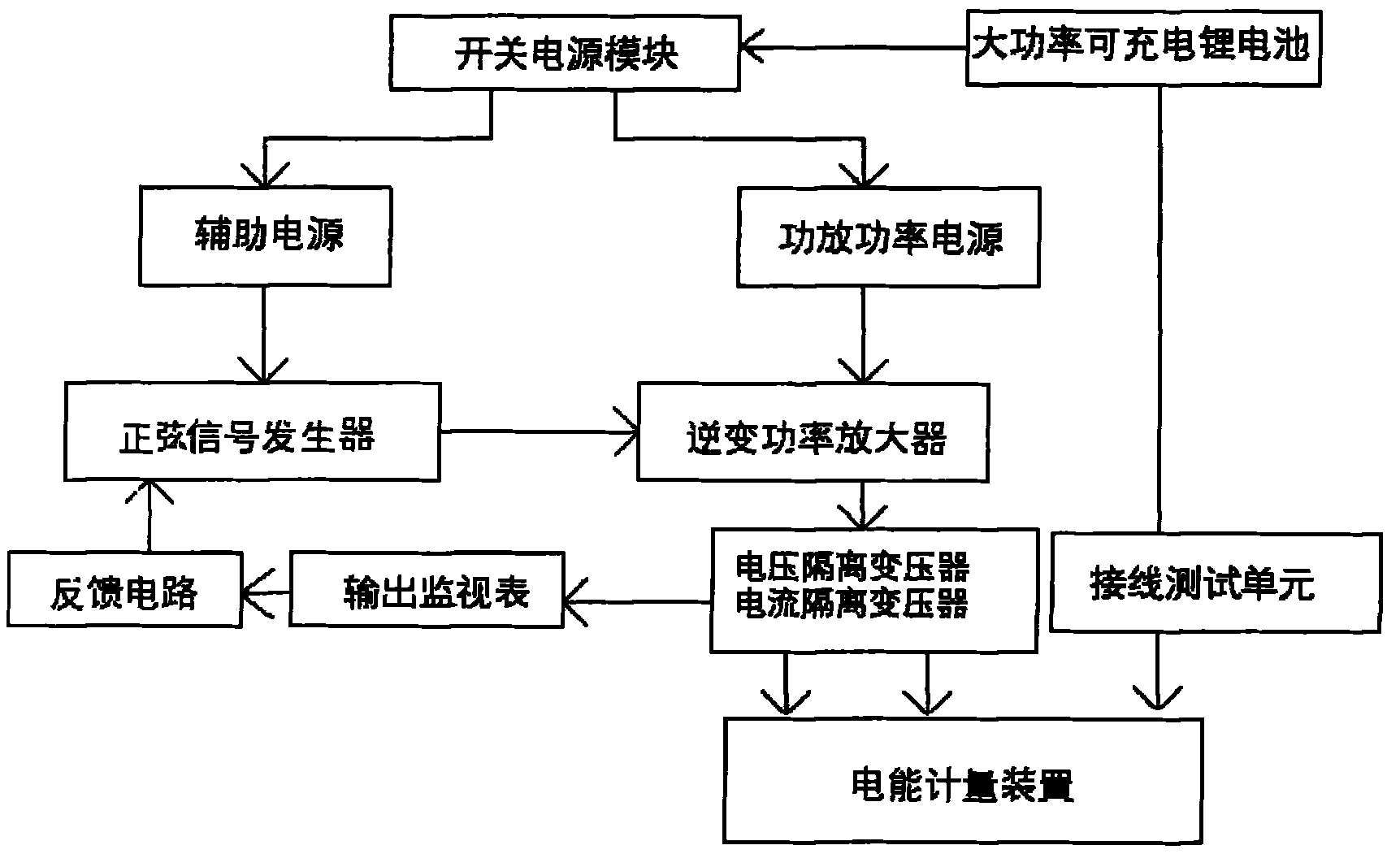
[0022] A wiring tester for an electric energy metering device, comprising a casing, a wiring test unit is arranged in the casing, and an analog power source unit is also arranged in the casing; the analog power source unit includes a battery and an inverter circuit, and the output terminal of the battery Connect the DC input end of the inverter circuit, the AC output end of the inverter circuit is the output end of the analog power source unit; the output end of the battery is also connected to the power input end of the wiring test unit. The battery in this example uses a rechargeable lithium battery with a voltage of +35V and -35V.

[0023] The inverter circuit includes a switching power supply module, a sinusoidal signal generator, an inverter power amplifier and an isolation transformer;

[0024] The DC input terminal of the switching powe...


PUM


Abstract

The invention discloses a connection testing device of an electric energy metering device. The connection testing device comprises a shell in which a connection testing unit and an analog power source unit are arranged, wherein the analog power source unit comprises a battery and an inverter circuit; the output end of the battery is connected with a direct current input end of the inverter circuit; an alternating current output end of the inverter circuit is an output end of the analog power source unit; and the output end of the battery is also connected with a power input end of the connection testing unit. The using method of the device comprises the following steps that: a secondary side of a voltage isolating transformer of the device is connected with a voltage connecting terminal of the electric energy metering device; the connection testing unit measures a corresponding current terminal; if the amplitude and the phase relation of each phase of measured voltage current are correspondingly consistent with the output of the device, the connection is correct; and if the amplitude and the phase relation of each phase of measured voltage current are inconsistent with the output of the device, the connection is false. By the device and the method, the problems that an external power supply is not arranged on site to supply power, the device is inconvenient to carry, detected equipment is not provided with a high-voltage transformer and the voltage current is not given or detected during detection of electric energy metering equipment are solved.

Description

technical field [0001] The invention belongs to measuring instruments, in particular to a wiring test device and a using method of an electric energy metering device. Background technique [0002] In the measurement process of electric energy metering devices (such as electric energy meters), at present, the meter installation and wiring personnel can only use a multimeter to roughly test whether the wiring of the electric energy meter is connected before the power metering cabinet is closed and the power supply is not available on site. Correct, sometimes you have to remove the stitches to check. This method is inconvenient, inaccurate, and prone to human errors. In the existing technology, there are mainly four problems: no external power supply on site, heavy weight for portability, efficiency improvement to achieve energy saving, whether the inspected equipment has a high-voltage transformer, voltage and current setting and detection. Contents of the invention [0003...

Claims


Application Information

Patent Timeline
Patent Type & Authority Applications(China)
IPC IPC(8): G01R31/02
Inventor 谭瑾梁吉军王坚张美华金在东覃述银
Owner JIANGSU ELECTRIC POWER CO
Learn More