Coin processing device

A technology for processing devices and coins, which is applied in coin receiving devices, coin counting, coin inspection, etc., can solve the problems of reduced friction of elastic parts, reduced coin processing efficiency, and insufficient reliability of coin transmission, and achieves the goal of improving processing efficiency Effect

Inactive Publication Date: 2011-05-25
OKI ELECTRIC IND CO LTD
View PDF7 Cites 9 Cited by
  • Summary
  • Abstract
  • Description
  • Claims
  • Application Information

AI Technical Summary

Problems solved by technology

[0006] However, there is the following problem in the technology of the above-mentioned conventional patent document 1: in the sorting unit, since the coins clamped between the elastic members such as urethane rubber on the outer peripheral portion of the rotary transmission disc and the fixed disc are The upper surface of the fixed disk slides for conveyance, so the coin dust caused by the sliding between the coin and the fixed disk adheres to the elastic member, reducing the friction of the elastic member, and the reliability of coin conveyance is insufficient, resulting in the loss of coins. Reduced processing efficiency
[0007] In addition, in the technology of Patent Document 2, there is the following problem: Since the coin storage unit picks up and conveys a plurality of coins dropped into the lower part of the case one by one, if the coins hang on the corner of the rotating coin storage unit , the coin will jump up and not be stored in the coin storage section, forming an empty coin storage section, making the reliability of coin transmission insufficient, resulting in a decrease in coin handling efficiency

Method used


Image

  • Coin processing device
  • Coin processing device
  • Coin processing device

Examples


Embodiment 1

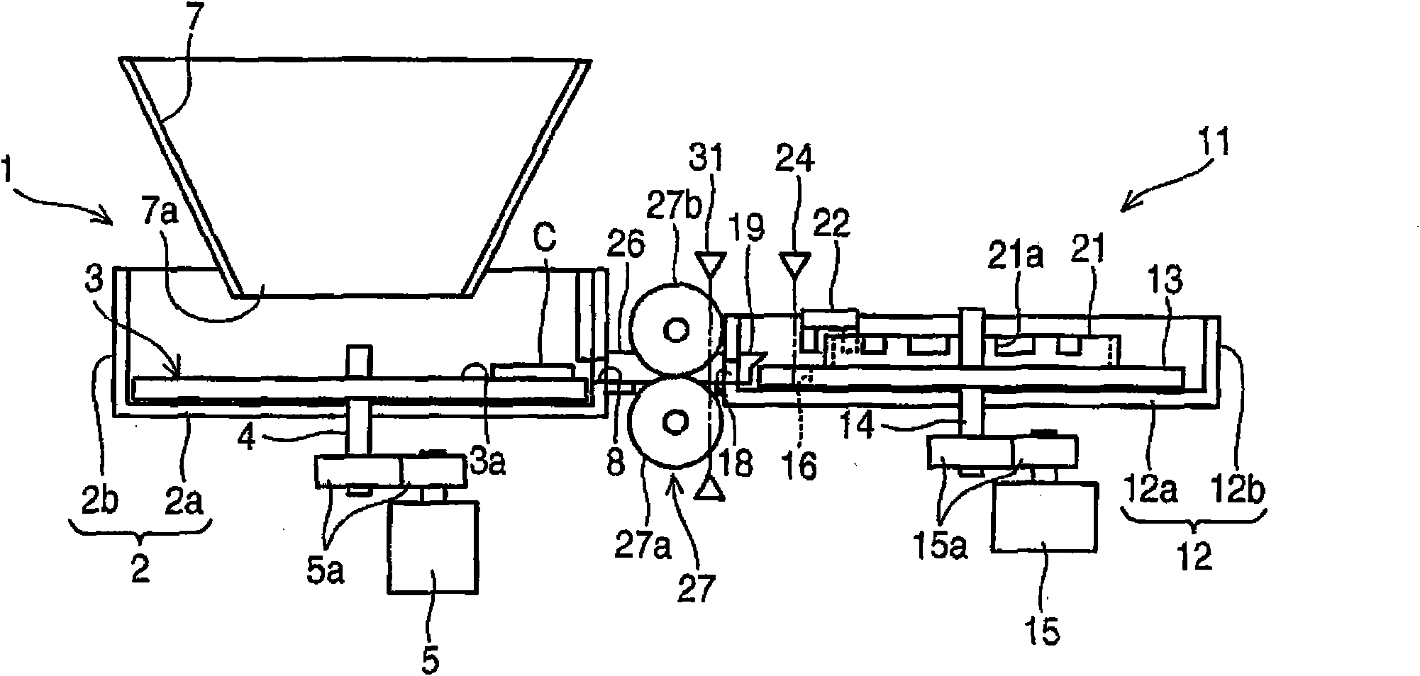
[0067] figure 1 , figure 2 Center 1 is the lead-out unit of the coin handling device.

[0068] 2 is the lead-out case of the lead-out unit 1, which is a bottomed cylindrical member having a height capable of accommodating approximately 100 or more coins C, and its bottom plate 2a is arranged horizontally.

[0069] 3 is a deriving rotary disk, which is horizontally arranged in the deriving housing 2, and is centered on the rotating shaft 4 supported in the center of the bottom plate 2a of the deriving housing 2 to the deriving direction ( figure 2The disk rotating in the counterclockwise direction) has a diameter such that a gap that cannot sandwich the coin C of the minimum thickness among the coins C to be processed is formed between the inner peripheral surface of the side wall 2b of the outlet case 2. The diameter is rotationally driven by the drive force transmitted from the lead-out motor 5 serving as a disk drive source to the rotary shaft 4 through the gear train 5...

Embodiment 2

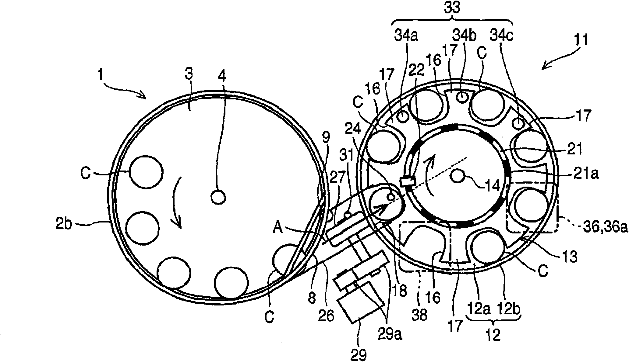
[0154] Next, use Figure 10 and Figure 11 The coin handling device of this embodiment will be described.

[0155] In addition, the same parts as in the above-mentioned first embodiment are given the same symbols and their descriptions are omitted.

[0156] The coin handling apparatus of this embodiment has the same configuration as that of the first embodiment described above.

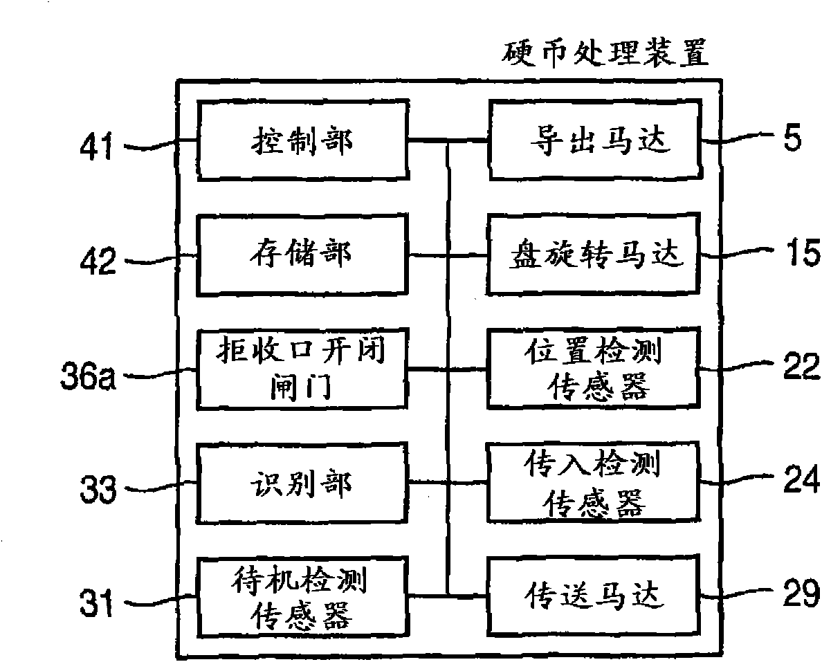
[0157] In addition, although the operation of the coin sorting process is the same as that of the above-mentioned embodiment 1 in principle, it is different from the above-mentioned embodiment 1 in that the following abnormal control is performed. Figure 5 As shown in the fifth coin C displayed, the control unit 41 temporarily stops feeding the conveying roller pair after passing the feeding end determination time T5 from when the feeding detection sensor 24 detects the fed coin C (ON). 27 of the drive, when using the standby detection sensor 31 to confirm the existence of the standby coin thereaf...

Embodiment 3

[0171] Next, use Figure 12 and Figure 13 The coin handling device of this embodiment will be described.

[0172] In addition, the same code|symbol is attached|subjected to the same part as the said Example 1, and the description is abbreviate|omitted.

[0173] The coin handling apparatus of this embodiment has the same configuration as that of the first embodiment described above.

[0174] In addition, it is different from the first embodiment in that the operation of the coin sorting process is changed in the stopping time of the drive of the conveyance plate 13 . Therefore, the intermittent driving in this embodiment is not intermittent driving of a fixed period, but non-periodic intermittent driving in which the driving of the stopped conveying tray 13 is started when the driving of the conveying roller pair 27 holding the waiting coins is stopped. In addition, the driving time of about one pitch of the coin storage unit 16 , that is, the driving time based on the stop...


PUM


Abstract

The invention provides a coin processing device, comprising: a leading-out unit provided with a separating door separating and leading out coins thrown onto a leading-out rotating circular disc configured in a leading-out housing horizontally configured one by one; a sorting unit configured in a sorting housing horizontally configured, and provided with a plurality of transmission discs of coin receiving parts separated by separating disposing parts and formed at an outer circumferential edge part and transmitting inlets making the coins transmitted to the coin receiving part pass through; a coin channel connecting the separating door of the leading-out unit and the transmitting inlet of the sorting unit and horizontally configured; and a pair of transmission roller pair configured at an upstream side of the coin channel and a coin transmitting inlet direction of the transmitting inlet and used for clamping the transmitted coins and making the coins be on standby at a standby position, wherein, intermittent drive of the transmission discs is performed, when the coin receiving parts of the transmission discs are stopped at a coin transmitting inlet position relative to the transmitting inlets, rotate the transmission roller pair and transmit the coins on standby at the standby position to the coin receiving parts.

Description

technical field [0001] The present invention relates to a coin handling device that connects a delivery unit that takes out coins thrown onto a rotary disk one by one and a sorting unit that stores the taken out coins and sorts the coins through a coin passage. Background technique [0002] A conventional coin handling device is provided with: a discharge unit having a discharge port for withdrawing coins one by one; elastic members such as urethane rubber that are provided on the outer peripheral edge of an inclined rotary conveying disk for clamping the coins introduced from the introduction port; A sorting unit that transfers between fixed discs with multiple sorting holes and discharge holes; an inclined coin channel that connects the discharge port of the export unit and the inlet of the sorting unit, and uses coins exported from the discharge port The inclination of the channel is transmitted to the inlet of the sorting unit by the gravity of the coin itself, and the c...

Claims


Application Information

Patent Timeline
Patent Type & Authority Applications(China)
IPC IPC(8): G07D5/00
CPCG07D3/14G07D9/008G07D11/22G07D2201/00
Inventor 青木正人箭野达也
Owner OKI ELECTRIC IND CO LTD
Why Eureka
Try Eureka