Magnetic saturation reactor

A technology of reactor and reactance coil, which is applied in the direction of inductance with magnetic core, transformer/inductor coil/winding/connection, etc., to achieve the effects of weight reduction, low reactance value, and reduced voltage loss

Inactive Publication Date: 2011-05-25
SHANDONG UNIV
View PDF4 Cites 14 Cited by
  • Summary
  • Abstract
  • Description
  • Claims
  • Application Information

AI Technical Summary

Problems solved by technology

There are disadvantages in the structure of the saturable react...

Method used


Image

  • Magnetic saturation reactor
  • Magnetic saturation reactor
  • Magnetic saturation reactor

Examples


Embodiment Construction

[0021] The present invention will be further described below in conjunction with the accompanying drawings.

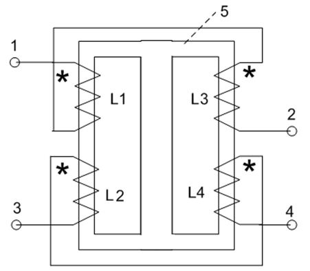
[0022] The structure and connection method of the magnetic saturation reactor are as follows: figure 1 shown. The AC terminal I1 and the AC terminal II2 of the device are connected in series to the AC transmission circuit; the DC terminal I3 and the DC terminal II4 of the device are connected in series to the DC power supply circuit.

[0023] Since the end of the same name of the reactance coil L1 is the AC terminal I1 of the AC circuit of the magnetic saturation reactor, the end of the opposite name of the reactance coil L1 is connected to the end of the same name of the reactance coil L3, and the end of the same name of the reactance coil L3 is the terminal of the AC circuit of the magnetic saturation reactor. AC terminal II; and because the structure, number of turns, and winding method of the reactance coil L1 and the reactance coil L3 have the same technical requ...


PUM


Abstract

The invention relates to a magnetic saturation reactor, which can reduce the volume and the weight of the magnetic saturation reactor under the condition of meeting performance requirements and can reduce the reactance of the magnetic saturation reactor in a magnetic saturation state. The magnetic saturation reactor comprise a theta-shaped structural magnetic saturation reactor core, wherein a reactive coil L1 and a direct current coil L2 are respectively arranged on one side of the magnetic saturation reactor; a reactive coil L3 and a direct current coil L4 are respectively arranged on the other side of the magnetic saturation reactor; the corresponding end of the reactive coil L1 is one alternating current terminal I of an alternating current loop of the magnetic saturation reactor; the unlike end of the reactive coil L1 is connected with the corresponding end of the reactive coil L3; the unlike end of the reactive coil L3 is the other alternating current terminal II of the alternating current loop of the magnetic saturation reactor; the corresponding end of the direct current coil L2 is connected with the corresponding end of the direct current coil L4; the unlike end of the direct current coil L2 is one direct current terminal I of the alternating current loop of the magnetic saturation reactor; and the unlike end of the direct current coil L4 is the other direct current terminal II of the alternating current loop of the magnetic saturation reactor.

Description

[0001] technical field [0002] The invention relates to the field of power transmission and transformation in power systems, in particular to a magnetic saturation reactor. Background technique [0003] With the continuous development of the power system and the continuous increase of power generation capacity, the short circuit current caused by the short circuit of the power system is very large. The short circuit current caused by the short circuit in the power system is very harmful to the power system. When a short circuit occurs in the power system, the relay protection device issues a trip command to trip the circuit breaker and cut off the short circuit current. The ability of the circuit breaker to cut off the short-circuit current is limited. When the short-circuit current exceeds the maximum cut-off current value of the circuit breaker, the circuit breaker cannot cut off the short-circuit current. Therefore, reducing the short-circuit current can enable the cir...

Claims


Application Information

Patent Timeline
IPC IPC(8): H01F17/04H01F27/28
Inventor 李晓明
Owner SHANDONG UNIV
Why Eureka
Try Eureka