Low-noise saturable reactor

A reactor and low-noise technology, applied in transformer/inductor cores, transformer/inductor coils/windings/connections, inductors with magnetic cores, etc., can solve the problem that high-order harmonic current cannot flow and the noise is large , iron core high-frequency vibration and other problems, to achieve the effect of low reactance value, low noise and good voltage waveform

Inactive Publication Date: 2011-09-14
SHANDONG UNIV
View PDF4 Cites 0 Cited by
  • Summary
  • Abstract
  • Description
  • Claims
  • Application Information

AI Technical Summary

Problems solved by technology

However, the reactance coil of the saturable reactor is connected in series, the high-order harmonic current cannot flow, the iron core generates high-frequency vibration, and the noise is large

Method used


Image

  • Low-noise saturable reactor
  • Low-noise saturable reactor
  • Low-noise saturable reactor

Examples


Embodiment 1

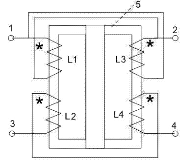
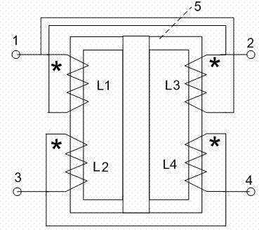
[0024] The structure and connection method of the saturated reactor are as follows: figure 1 shown. The AC terminal I1 and the AC terminal II2 of the device are connected in series to the AC transmission circuit; the DC terminal I3 and the DC terminal II4 of the device are connected in series to the DC power supply circuit.

[0025] Since the same-named end of the reactance coil L1 is connected to the opposite-named end of the reactance coil L3, it is one of the AC terminals I1 of the AC circuit of the saturable reactor, and the opposite-named end of the reactance coil L1 is connected to the same-named end of the reactance coil L3, which is a saturated reactor. Another AC terminal II2 of the AC circuit; and because the structure, number of turns, and winding method of the reactance coil L1 and the reactance coil L3 have the same technical requirements; therefore, the AC current flowing through the reactance coil L1 generates a magnetic flux Φ1 in the iron core The magnetic fl...

Embodiment 2

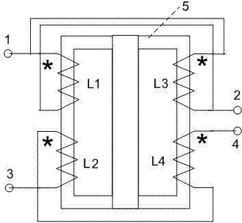
[0033] figure 2 Indicates another saturable reactor connection method with less noise; it includes a saturable reactor core; one side of the saturable reactor core is respectively equipped with a reactance coil L1 and a DC coil L2; the other side of the saturable reactor core is respectively corresponding to Install the reactance coil L3 and the DC coil L4; the reactance coil L1 has the same structure and the number of turns as the reactance coil L3; the DC coil L2 has the same structure and the number of turns as the DC coil L4;

[0034] The same-named end of the reactance coil L1 is connected to the same-named end of the reactance coil L3, and serves as one of the AC terminals I1 of the AC circuit of the saturated reactor; Another AC terminal II2 of the AC circuit of the device;

[0035] The same-named end of the DC coil L2 is connected to the different-named end of the DC coil L4. At the same time, the different-named end of the DC coil L2 is used as one of the DC termina...


PUM


Abstract

The invention relates to a low-noise saturable reactor, which can lower the reactance value of the saturable reactor in saturated state. The low-noise saturable reactor comprises a saturable reactor iron core, wherein a reactance coil L1 and a direct-current coil L2 are arranged on one side of the saturable reactor iron core; a reactance coil L3 and a direct-current coil L4 are arranged on the other side of the saturable reactor iron core; the reactance coil L1 and the reactance coil L3 have the same structure and the same number of turns; the direct-current coil L2 and the direct-current coil L4 have the same structure and the same number of turns; the homonymous end of the reactance coil L1 is connected with the synonymous end of the reactance coil L3 and is taken as an alternating-current terminal I of a saturable reactor alternating-current loop; the synonymous end of the reactance coil L1 is connected with the homonymous end of the reactance coil L3 and is taken as another alternating-current terminal II of the saturable reactor alternating-current loop; the homonymous end of the direct-current coil L2 is connected with the synonymous end of the direct-current coil L4 and is taken as a direct-current terminal I of a saturable reactor direct-current loop; and the synonymous end of the direct-current coil L4 is taken as another direct-current terminal II of the saturable reactor direct-current loop.

Description

[0001] technical field [0002] The invention relates to the field of electric power transmission and transformation, in particular to a low-noise saturated reactor. Background technique [0003] With the continuous development of the power system and the continuous increase of power generation capacity, the short circuit current caused by the short circuit of the power system is very large. The short circuit current caused by the short circuit in the power system is very harmful to the power system. Reducing the short-circuit current can enable the circuit breaker to cut off the short-circuit current, reduce the damage of power equipment during short-circuit, and improve the stability of the power system. [0004] In recent years, research on methods and devices for limiting short-circuit current (also known as current limiters) has become a hot topic. [0005] The current limiter is formed by using the saturation characteristic of the saturable reactor core. A group of ...

Claims


Application Information

Patent Timeline
Patent Type & Authority Applications(China)
IPC IPC(8): H01F17/04H01F27/28H01F27/24
Inventor 李晓明
Owner SHANDONG UNIV
Why Eureka
Try Eureka