Ultra-wideband antenna with microstrip line

An ultra-wideband antenna and microstrip line technology, which is applied to antennas, resonant antennas, loop antennas, etc., can solve the problems of large impedance span, high frequency, and narrowband antennas cannot solve ultra-wideband antennas, so as to reduce usage and optimize reactance. effect of value

Active Publication Date: 2021-03-12
HANGZHOU DIANZI UNIV
View PDF14 Cites 0 Cited by
  • Summary
  • Abstract
  • Description
  • Claims
  • Application Information

AI Technical Summary

Problems solved by technology

The frequency bandwidth will lead to a larger impedance span, and the problem of higher frequency will appear one after another. However, the impedance matching of the narrowband antenna cannot solve th

Method used


Image

  • Ultra-wideband antenna with microstrip line
  • Ultra-wideband antenna with microstrip line
  • Ultra-wideband antenna with microstrip line

Examples


Embodiment Construction

[0028] In order to make the object, technical solution and advantages of the present invention clearer, the present invention will be further described in detail below in conjunction with the accompanying drawings and embodiments. It should be understood that the specific embodiments described here are only used to explain the present invention, not to limit the present invention.

[0029] On the contrary, the invention covers any alternatives, modifications, equivalent methods and schemes within the spirit and scope of the invention as defined by the claims. Further, in order to make the public have a better understanding of the present invention, some specific details are described in detail in the detailed description of the present invention below. The present invention can be fully understood by those skilled in the art without the description of these detailed parts.

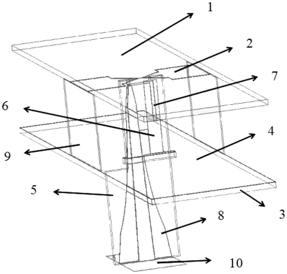
[0030] see figure 1 , which is a schematic structural diagram of an ultra-wideband antenna of a micro...


PUM


Abstract

The invention discloses an ultra-wideband antenna with a microstrip line, and the antenna comprises an upper dielectric substrate, a radiation patch, an open-circuit line, a short-circuit line, a ground plane, a lower dielectric substrate, a straight dielectric substrate, an isolation wall, a hyperbolic microstrip balun feeder line and an ideal wave port, wherein the radiation patch covers the lower surface of the upper dielectric substrate; the ground plane covers the upper surface of the lower dielectric substrate; the short-circuit line covers the rear surface of the straight dielectric substrate; the open-circuit line covers the front surface of the straight dielectric substrate; the hyperbolic microstrip Balun feeder lines cover the front surface and the rear surface of the straight dielectric substrate; the isolation wall is perpendicular to the tail end of the radiation patch and is arranged between the upper dielectric substrate and the lower dielectric substrate; and the idealwave port is arranged below the hyperbolic microstrip Balun feeder line. The method comprises the following steps: connecting an antenna and a short-circuit line in parallel to reduce the reactance value in a frequency band; connecting the antenna with an open-circuit line in series, so that the reactance value in the frequency band is further reduced; and finally, matching the resistance througha hyperbolic microstrip Balun feeder line to achieve the purpose.

Description

technical field [0001] The invention belongs to the technical field of antennas, and relates to an ultra-wideband antenna of a microstrip line. Background technique [0002] With the continuous development of scientific progress and the continuous improvement and development of electronic communication systems, new requirements are put forward for the transmission capability of antennas. Antennas with wide frequency band, wide angle scanning, and good polarization performance have become the current research hotspots. Microstrip antennas are now widely used in modern communications due to their simple structure, light weight, miniaturization, broadband, and easy connection to microstrip feed networks. In recent years, with the popularity of wireless communication products, the development of ultra-wideband technology. People put forward higher and higher requirements on the bandwidth of the antenna. Since 2002, the Federal Communications Commission passed a resolution to a...

Claims


Application Information

Patent Timeline
IPC IPC(8): H01Q1/38H01Q1/48H01Q1/50H01Q1/52H01Q5/10H01Q5/335
CPCH01Q1/38H01Q1/50H01Q1/521H01Q1/48H01Q5/10H01Q5/335H01Q7/00H01Q1/523H01Q5/25H01Q9/045
Inventor 程知群王振何若愚高鹏
Owner HANGZHOU DIANZI UNIV
Why Eureka
Try Eureka