Intelligent reactive compensation comprehensive control device

A comprehensive control and intelligent technology, applied in reactive power compensation, reactive power adjustment/elimination/compensation, circuit devices, etc., which can solve the problems of single control criterion and simple function.

Active Publication Date: 2011-05-25
SUZHOU WANLONG ELECTRIC GROUP
View PDF4 Cites 44 Cited by
  • Summary
  • Abstract
  • Description
  • Claims
  • Application Information

AI Technical Summary

Problems solved by technology

[0004] In order to overcome the shortcomings of single control criterion and simple function of the existing reactive power compensation controller, the present invention provides an intelligent reactive power compensation comprehensive control device, which uses grid reactive power or grid power factor as the control capacitor bank According to the criterion of switching and cutting, the voltage is used as the constraint condition, and according to the measured three-phase total reactive power and the reactive power of each phase, the most suitable compensation control strategy (three-phase common compensation or separate compensation) and the most suitable compensation control strategy are selected. Optimal compensation capacity, to select the most suitable capacitor bank for switching and switching control, so as to minimize the reactive power exchange of transmission and distribution lines, which can effectively improve the power factor of the grid and avoid over-compensation or under-compensation , and ensures the voltage quality of the power grid, and is also conducive to energy saving and loss reduction

Method used


Image

  • Intelligent reactive compensation comprehensive control device
  • Intelligent reactive compensation comprehensive control device
  • Intelligent reactive compensation comprehensive control device

Examples


Embodiment Construction

[0037] In order to make the object, technical solution and advantages of the present invention clearer, the present invention will be further described in detail below in conjunction with the accompanying drawings and embodiments. It should be understood that the specific embodiments described here are only used to explain the present invention, not to limit the present invention.

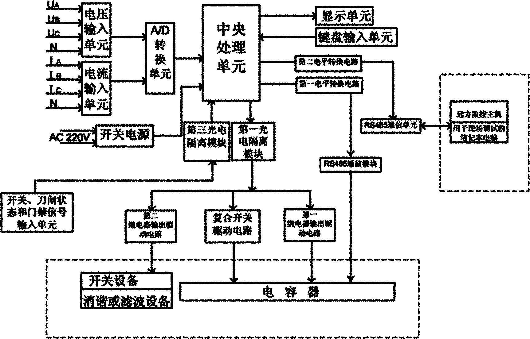
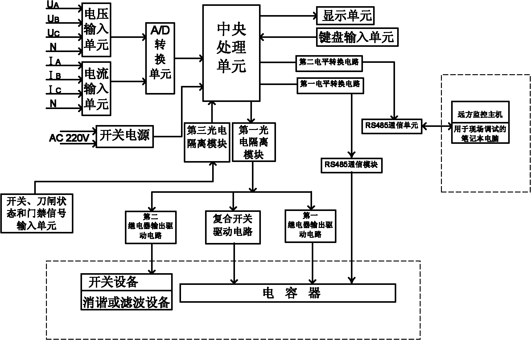
[0038] Such as figure 1 As shown, the intelligent reactive power compensation comprehensive control device includes a voltage input unit, a current input unit, an A / D (analog / digital) conversion unit, a central processing unit, a switching power supply, a compensation capacitor switching outlet drive unit, and the like. The voltage input unit includes a voltage transformer and a signal processing circuit with level conversion and filtering functions, which are used to convert the input three-phase voltage into the weak electric signal required by the A / D conversion unit; the current input unit incl...


PUM


Abstract

The invention provides an intelligent reactive compensation comprehensive control device, wherein a judging process of a judging module in a central processing unit is as follows: 1, judging whether to switch on or switch off according to reactive power or power factor of an electric grid; 2, judging whether voltages in three phases are all in a range of allowing the switching on or the switchingoff; 3, calculating a vacancy value or an excess value of total reactive power, and selecting a total compensation capacitor group; 4, calculating the vacancy value or the excess value of the reactive power of each phase, and selecting an individual compensation capacitor group; 5, judging whether the capacitor group is in blocking state; and 6, outputting switching on or switching off instructions to a switching outlet driving unit of the compensation capacitor. The control device uses the reactive power or the power factor of the electric grid as criterion for controlling the switching on or the switching off of the capacitor groups, uses the voltage as a constraint condition, and uses the vacancy or the excess of the reactive power to preferentially select a reactive power compensationpolicy and the capacitor groups to be switched, so that the power factor of the electric grid can be effectively improved, losses of the electric grid can be reduced, and voltage quality of the electric grid is ensured.

Description

technical field [0001] The invention relates to a control device in the field of electric power technology, in particular to an intelligent reactive power compensation comprehensive control device suitable for distribution transformers or 24kV-220V feeder lines. Background technique [0002] In industrial, agricultural and domestic electricity loads, there are many inductive loads, such as: asynchronous motors, transformers, fluorescent lamps, etc. In addition to consuming active power, inductive loads also need to absorb a large amount of reactive power from the grid. The power factor is very low. For example, the power factor of the fluorescent lamp load is only about 0.54, the power factor of electric fans, washing machines, radio recorders, refrigerators, etc. is about 0.65-0.85, and the power factor of small industrial users is even worse. Reactive power loss, therefore, the power factor of the entire low-voltage distribution network is low. The reactive power consume...

Claims


Application Information

Patent Timeline
Patent Type & Authority Applications(China)
IPC IPC(8): H02J3/18H02J3/01H02J13/00
CPCY04S10/22Y02E40/30Y02E40/74Y02E40/40Y02E40/70
Inventor 黄益庄吕恭祥
Owner SUZHOU WANLONG ELECTRIC GROUP
Why Eureka
Try Eureka