Interconnection method of transparent interconnection network of lots of links in different places and operator edge device

A transparent interconnection and multi-link technology, applied in the field of network interconnection, can solve problems such as slow convergence, waste of bandwidth, and traffic impact

Inactive Publication Date: 2011-05-25
NEW H3C TECH CO LTD
View PDF1 Cites 43 Cited by
  • Summary
  • Abstract
  • Description
  • Claims
  • Application Information

AI Technical Summary

Problems solved by technology

[0002] In traditional Layer 2 networks, Spanning Tree Protocol (STP, Spanning Tree Protocol) is used to block loops, which wastes bandwidth and cannot load share. Packets do not carry Time to Live (TTL, Time to Live) parameters. broadcast storm
And STP convergence is relatively slow, which has a great impact on traffic
In addition, topology changes have an impact on the entire network
figure 1 An example diagram of an existing STP-based Layer 2 network is given, such as figure 1 As shown, the link between B3 and B4 is blocked by STP, resulting in wasted bandwidth
[0003] figure 2 The typical networking of the data center Layer 2 network is given, such as figure 2 As shown, each device partition (PoD, Position of Device) has a large number of access switches and several aggregation switches, during which redundant loops are eliminated through STP, and aggregation achieves point-to-point load sharing and high reliability. The disadvantages are Convergence is slow after topology changes, STP blocks redundant loops, resulting in wasted bandwidth, and temporary loops exist, which cannot effectively implement load sharing of redundant links, and link bottlenecks are prone to occur. It is also necessary to learn a large number of Media Access Control (MAC, Media Access Control) addresses, and the burden is relatively high
If VPLS, OTV and other technologies are used to interconnect data centers, the TRILL networks of the two data centers are independent of each other, and the TRILL path calculations are irrelevant, that is, the remote interconnection of TRILL networks cannot be realized

Method used


Image

  • Interconnection method of transparent interconnection network of lots of links in different places and operator edge device
  • Interconnection method of transparent interconnection network of lots of links in different places and operator edge device
  • Interconnection method of transparent interconnection network of lots of links in different places and operator edge device

Examples


Embodiment Construction

[0067] The present invention will be further described in detail below in conjunction with the accompanying drawings and specific embodiments.

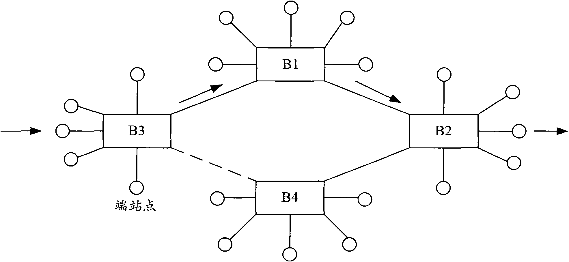
[0068] Figure 10 A schematic diagram of Layer 2 networking for remote interconnection of TRILL networks provided by the embodiment of the present invention, as shown in Figure 10 As shown, sites 1 and 2 are remote sites of the same VPN: VPN A, and sites 3 and 4 are remote sites of the same VPN: VPN B. Sites 1, 2, and sites 3 and 4 realize remote interconnection through MPLS L3VPN.

[0069] In practical applications, each TRILL network may contain more VPN sites, and the network diagram at this time can be obtained by figure 2 It can be obtained by simple expansion, and will not be drawn one by one here.

[0070]The following gives the specific implementation of remote sites such as: site 1, 2, site 3, 4 how to achieve remote interconnection:

[0071] Figure 11 The flow chart of the TRILL network remote interconnection method p...


PUM


Abstract

The invention discloses an interconnection method of a transparent interconnection network of lots of links in different places and an operator edge device, wherein a first site and a second site belong to the same VPN (Virtual Private Network), implement interconnection in different places through an MPLS (Multiple Protocol Label Switching) L3VPN (Layer-3 Virtual Private Network), and respectively achieve the access to the MPLS L3VPN through a first PE (Provider Edge) and a second PE, a first CE (Customer Edge) and a second CE are respectively located at the first site and the second site, and a first RB and a second RB are respectively an optional RB under the first CE and the second CE; the method comprises the steps that: the first PE and the first CE interacts a TRILL (Transparent Interconnection of Lots of Links) IS-IS message to learn local TRILL route of the first RB, and transmit the local TRILL route of the first RB to the second PE after adding a VPN identifier; the second PE transmits the local TRILL route of the first RB to the second RB via the second CE; the second PE receives a TRILL data message of which the destination is the first RB, and transmits the message to the first PE according to the local TRILL route of the first RB, and the first PE transmits the message to the first RB according to the local TRILL route of the first RB. The interconnection method of the transparent interconnection network of lots of links in different places implements the interconnection of the TRILL network in different places.

Description

technical field [0001] The present invention relates to the technical field of network interconnection, in particular to a method for interconnecting networks in different places and a provider edge device (PE, Provider Edge) for Transparent Interconnection of Lots of Links (TRILL). Background technique [0002] In traditional Layer 2 networks, Spanning Tree Protocol (STP, Spanning Tree Protocol) is used to block loops, which wastes bandwidth and cannot load share. Packets do not carry Time to Live (TTL, Time to Live) parameters. Broadcast storm. In addition, STP converges slowly, which has a great impact on traffic. In addition, topology changes affect the entire network. figure 1 An example diagram of an existing STP-based Layer 2 network is given, such as figure 1 As shown, the link between B3 and B4 is blocked by STP, resulting in wasted bandwidth. [0003] figure 2 The typical networking of the data center Layer 2 network is given, such as figure 2 As shown, eac...

Claims


Application Information

Patent Timeline
Patent Type & Authority Applications(China)
IPC IPC(8): H04L12/56H04L12/46H04L45/50
Inventor 周万
Owner NEW H3C TECH CO LTD
Why Eureka
Try Eureka