
Device for installing and locking electrical appliance on cap type installation rail

A technology for installing rails and electrical appliances, applied in the direction of support structure installation, rack/frame structure, etc., can solve the problems of complex stopper structure, affecting the rationality of internal structure and product performance, and reducing internal space, so as to achieve convenient combination and Easy to manage and disassemble, and reliable installation

Active Publication Date: 2011-05-25
SHANGHAI NOARK ELECTRIC
View PDF5 Cites 6 Cited by
  • Summary
  • Abstract
  • Description
  • Claims
  • Application Information

AI Technical Summary

Problems solved by technology

However, since this installation and fixing device is mutually restricted by a locking hole groove at the bottom of the electrical appliance casing and a locking protrusion of the stopper, the electrical appliance is fixed on the mounting rail through the stopper, and the stopper is released by releasing the restrictive relationship. It can be translated along the installation rail. The groove structure at the bottom of the electrical appliance shell reduces the internal space of the product, which affects the rationality of the original internal structure and product performance to a certain extent.
Moreover, the structure of this stopper is complicated, and a part is added to limit its elastic member.

Method used


Image

  • Device for installing and locking electrical appliance on cap type installation rail
  • Device for installing and locking electrical appliance on cap type installation rail
  • Device for installing and locking electrical appliance on cap type installation rail

Examples


Embodiment Construction

[0019] Attached below Figures 1 to 5 The illustrated embodiments at different angles or under different assembly conditions further describe the device for installing locking electrical appliances on the hat-type mounting rail of the present invention, making its features and advantages easier to understand. The device for installing and fixing modularized electrical appliances that is convenient for loading and unloading of the present invention is not limited to the description of the following embodiments.

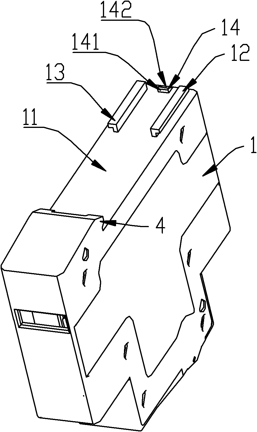
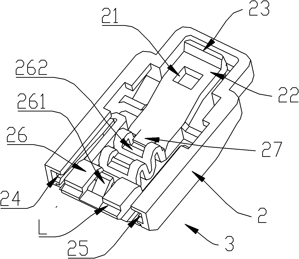
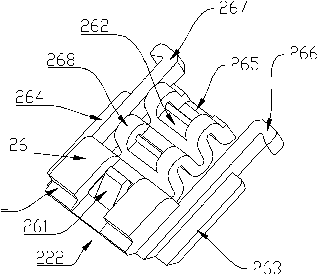
[0020] The device for installing a locking electrical appliance on a hat-type mounting rail of the present invention is composed of a housing 1 of a modular electrical appliance and a stopper 3 composed of a sliding piece 2 and an elastic piece 222 . The installation rail of the modular electrical appliance is a standard installation rail or a hat-type standardized installation rail. The shape of the installation rail is similar to a hat with a punched cap. The two sid...


PUM


Abstract

The invention relates to a device for installing and locking an electrical appliance on a cap type installation rail, which comprises a hanging hook fixedly formed at one end of an electrical appliance shell and an installation structure which is provided with a retainer, a first guide rail structure and a locking piece and is formed at the other end of the electrical appliance shell, wherein the retainer is connected with the electrical appliance shell by the first guide rail structure and can slide between positions in which the retainer is locked and disengaged with the installation rail by the locking piece, so that the installation structure and the hanging hook clamp and fix the electrical appliance to the installation rail through the common contact with two symmetrical bulged optical margins of the installation rail positioned between the installation structure and the hanging hook; a first guide rail groove is formed on the retainer, and the retainer is slidably arranged on the electrical appliance shell by the first guide rail which is fixedly arranged on the shell and can be inserted into the first guide rail groove; the retainer comprises a sliding piece and an elastic piece which can be assembled by a second guide rail structure; and the locking piece comprises a locking hole which is used for bearing a locking bulge and is formed on the head of the sliding piece, and by the elastic bias voltage of the elastic piece, the electric appliance is arranged and locked on the installation rail by the retainer.

Description

technical field [0001] The invention relates to a device that can conveniently install and fix modularized electrical appliances on a guide rail, in particular, it is suitable for installing and fixing or moving modularized electrical appliances on a modularized TH type (hat type) standardized mounting rail. device. Background technique [0002] Modular electrical appliances are a modular combination composed of terminal electrical appliances and their electrical, mechanical connections and protective casings. Terminal electrical appliances are electrical appliances installed at the end of power line circuits, used to monitor related circuits and electrical equipment For power distribution, control, protection, adjustment and alarm, etc., including switches, sockets, ammeters, leakage protectors, small circuit breakers, contactors, relays, monitors, etc., all parts of the modularized terminal electrical appliances are installed in the In the plastic shell, the plastic shell...

Claims


Application Information

Patent Timeline
IPC IPC(8): H05K7/14H05K7/18
Inventor 严鹏斌卢科军
Owner SHANGHAI NOARK ELECTRIC
Features
  • Generate Ideas
  • Intellectual Property
  • Life Sciences
  • Materials
  • Tech Scout
  • Unparalleled Data Quality
  • Higher Quality Content
  • 60% Fewer Hallucinations
Learn More