Adjustable strip-plating die

A mold and bar adjustment technology, which is applied in the field of adjustable bar plating molds, can solve the problems of large deformation of the screw rod, inaccurate relative position, large deformation, etc., and achieve the effect of increased rigidity, improved precision and good rigidity of the mold

Inactive Publication Date: 2012-05-23
曲悦峰
View PDF0 Cites 0 Cited by
  • Summary
  • Abstract
  • Description
  • Claims
  • Application Information

AI Technical Summary

Problems solved by technology

[0003] 1. The screw 10 is very long, and the middle is suspended, so the rigidity is very poor, and it is easy to deform under force. Therefore, the rigidity of the screw 10 is required to be very good. Only metal screws can be used to minimize deformation, but the deformation is still large
[0004] 2. The metal screw is conductive and not resistant to corrosion. After a period of use, metal crystals will be formed on the screw, or it will be corroded and thinned or even broken.
[0005] 3. It is difficult to process a sufficient length of the screw with too small diameter, and if the screw is too small, the rigidity is poor, and it is easy to be deformed by force; if the diameter is too large, it will block the electroplating solution, resulting in a decrease in the thickness of the coating at the blocked position
[0006] 4. Due to the large force and deformation of the screw, the coaxiality of the upper mold 70 and the lower mold 20 is poor, and the relative position is inaccurate
As a result, the height of the silicone rings of the upper mold 70 and the lower mold 20 is inconsistent, and there is a height difference H. The lower side of the mold cannot be in contact with the metal belt 30, resulting in leakage of the electroplating solution and expansion of the plating area, resulting in the scrapping of electroplating products and increasing the cost of electroplating chemicals. consume
[0007] 5. Since the upper mold 70 and the lower mold 20 are made of plastic, and the screw 10 is made of metal, their thermal expansion rates are inconsistent
The electroplating mold is usually stored at room temperature, and when it is in contact with a high-temperature electroplating solution, the nut 80 will loosen after repeated expansion and contraction, causing the width of the plating area to lose control

Method used


Image

  • Adjustable strip-plating die
  • Adjustable strip-plating die
  • Adjustable strip-plating die

Examples


Embodiment Construction

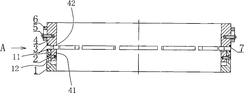
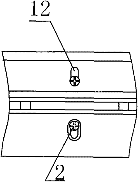
[0019] See figure 1 with figure 2 , figure 1 with figure 2 Disclosed is an adjustable strip plating mold, including a ring-shaped upper mold 4 and a ring-shaped lower mold 1 with the same diameter as the ring-shaped upper mold 4, and the ring-shaped upper mold 4 and the ring-shaped lower mold 1 A convex ring 41 is provided on the side in contact with the convex ring 41, a circle of water passing holes 42 is provided on the convex ring 41, and a threaded hole 43 is provided on the outside of the water passing hole 42. The ring-shaped upper mold 4 is provided with a concave ring 11 on the contact side. The ring-shaped lower mold 1 is provided with an axially elongated adjusting hole 12 relative to the threaded hole 43. The ring-shaped upper mold 4 The ring-shaped lower mold 1 is sleeved in a transitional fit through the convex ring 41 and the concave ring 11, and the screw 2 is screwed into the threaded hole 43 through the elongated adjusting hole 12, and the ring-shaped low...


PUM


Abstract

The invention discloses an adjustable strip-plating die which comprises an upper annular die and a lower annular die with same diameter as the upper annular die, wherein one side of the upper annular die, which is in contact with the lower annular die, is provided with a convex ring, a circle of water through holes are arranged on the convex ring, the outer side of each water through hole is provided with a threaded hole, one side of the lower annular ring, which is in contact with the upper annular die, is provided with a concave ring, the lower annular die is provided with an axial long regulating hole opposite to the thread holes, the upper annular die and the lower annular die are sleeved through the convex ring and the concave ring in transition matching manner, and screws are screwed in the threaded holes after passing through the long regulating hole so as to fixedly connect the lower annular die with the upper annular die together. Because the upper annular die and the lower annular die are embedded and matched, the rigidity of the die is greatly increased; meanwhile, the adjustable strip-plating die with critical dimension can be processed by once clamping so that the precision is improved.

Description

Technical field [0001] The invention relates to an adjustable strip plating mold. Background technique [0002] The electroplating mold is a special tool used for partial continuous electroplating of the lead frame (a metal strip) of electronic components. Its function is to ensure that the area that needs electroplating can be plated, and the area that does not need electroplating is not allowed to be plated. Traditional electroplating molds, such as image 3 with Figure 4 As shown, it uses a screw 10 and a nut 80 to connect the upper mold 70 and the lower mold 20. By adjusting the position of the nut 80, the distance between the upper mold 70 and the silicone ring 40 of the lower mold 20 is appropriate, and then the nut 80 is tightened. That's it. The edge of the plating area of ​​the electroplating mold is parallel to the edge of the lead frame, and is strip-shaped partial electroplating. The width of the plating area and the distance from the plating area to the edge of th...

Claims


Application Information

Patent Timeline
Patent Type & Authority Patents(China)
IPC IPC(8): C25D7/06
Inventor 曲悦峰
Owner 曲悦峰
Why Eureka
Try Eureka