Tire shape inspection method and tire shape inspection device

An inspection method, tire technology, applied to measuring devices, tire parts, optical devices, etc., can solve the difficulties of automatic setting, false detection of non-bump parts, and it is difficult to clearly distinguish the change of measured value of shape defects, etc. question

Active Publication Date: 2011-06-01
KOBE STEEL LTD
View PDF7 Cites 38 Cited by
  • Summary
  • Abstract
  • Description
  • Claims
  • Application Information

AI Technical Summary

Problems solved by technology

[0017] Therefore, the conventional shape defect inspection process that performs low-pass filter processing or differential smoothing processing on the measured value of the surface height of one line in the tire circumferential direction has the following problem: it is difficult to clearly distinguish the change in the measured value caused by the shape defect from the above-mentioned display mark. Measured value changes caused by
[0020] However, in the conventional shape defect inspection process, the measurement value of the non-protrusion part within a series of displayed mark outl

Method used


Image

  • Tire shape inspection method and tire shape inspection device
  • Tire shape inspection method and tire shape inspection device
  • Tire shape inspection method and tire shape inspection device

Examples


Embodiment Construction

[0165] Hereinafter, embodiments of the present invention will be described with reference to the drawings to facilitate understanding of the present invention. In addition, the following embodiment is a specific example of this invention, and does not limit the technical scope of this invention.

[0166] (the first invention)

[0167] First, refer to figure 1 , the overall configuration of the tire shape inspection device W according to one embodiment of the first invention will be described.

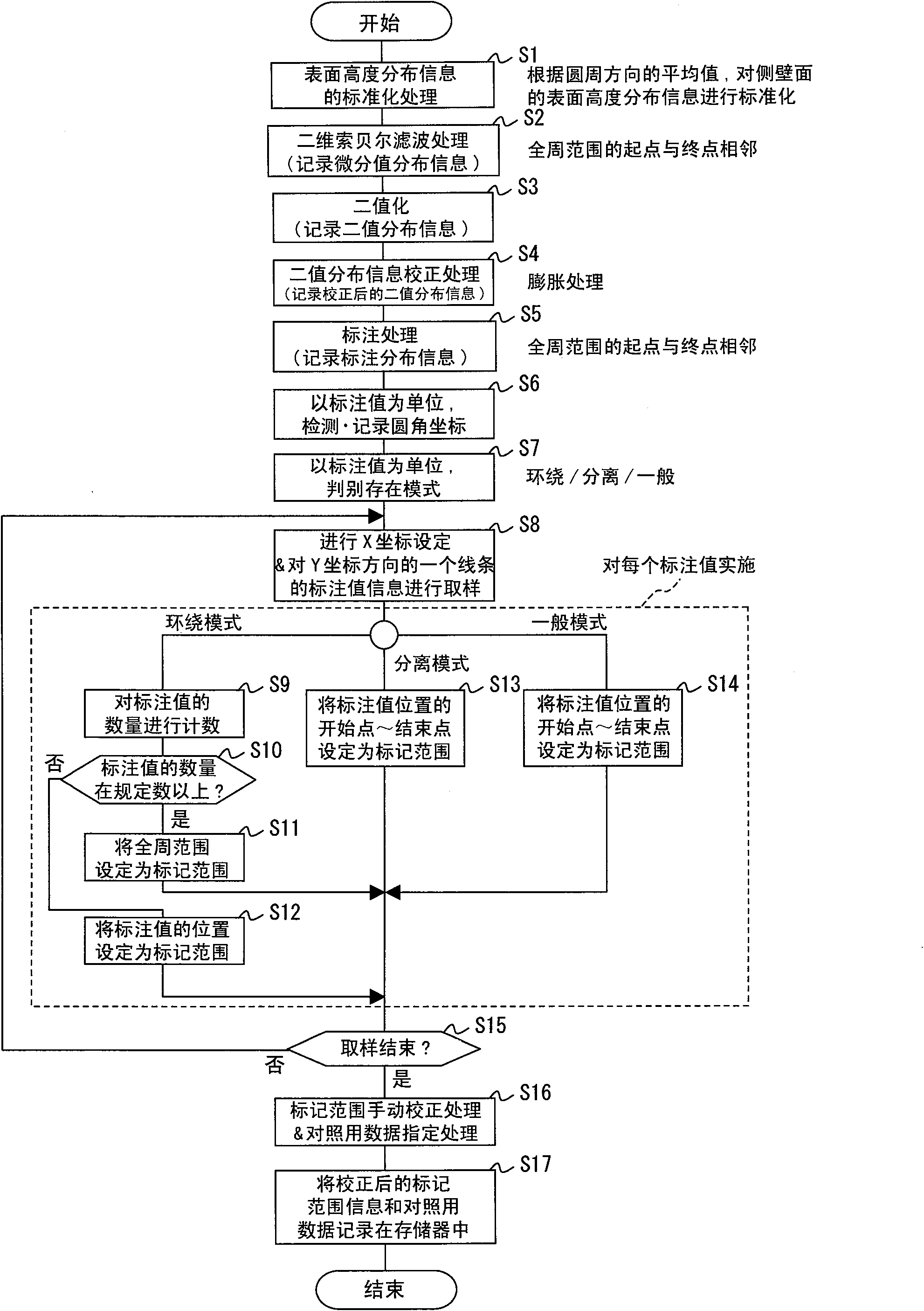
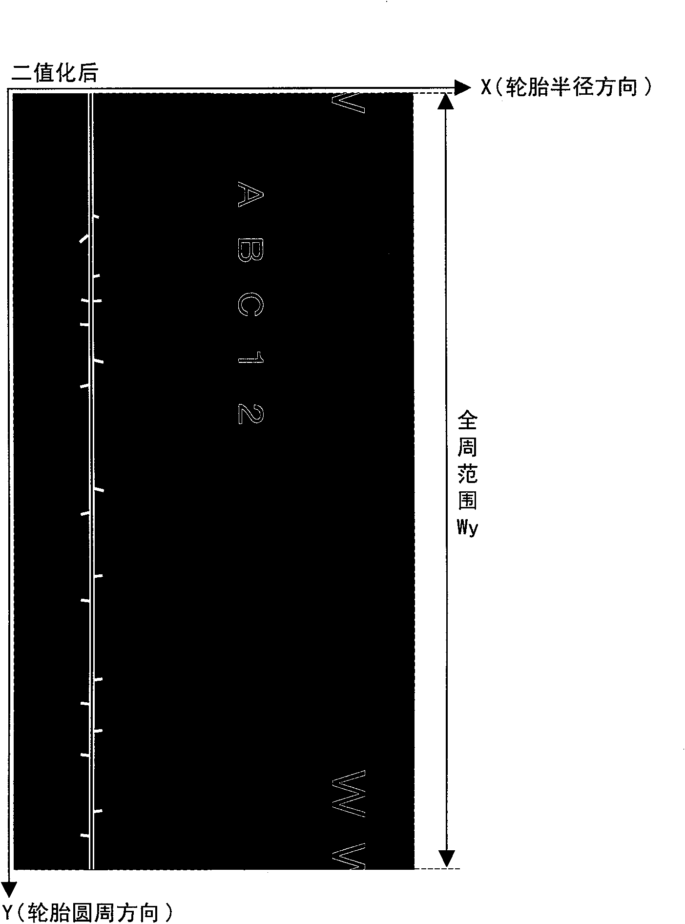
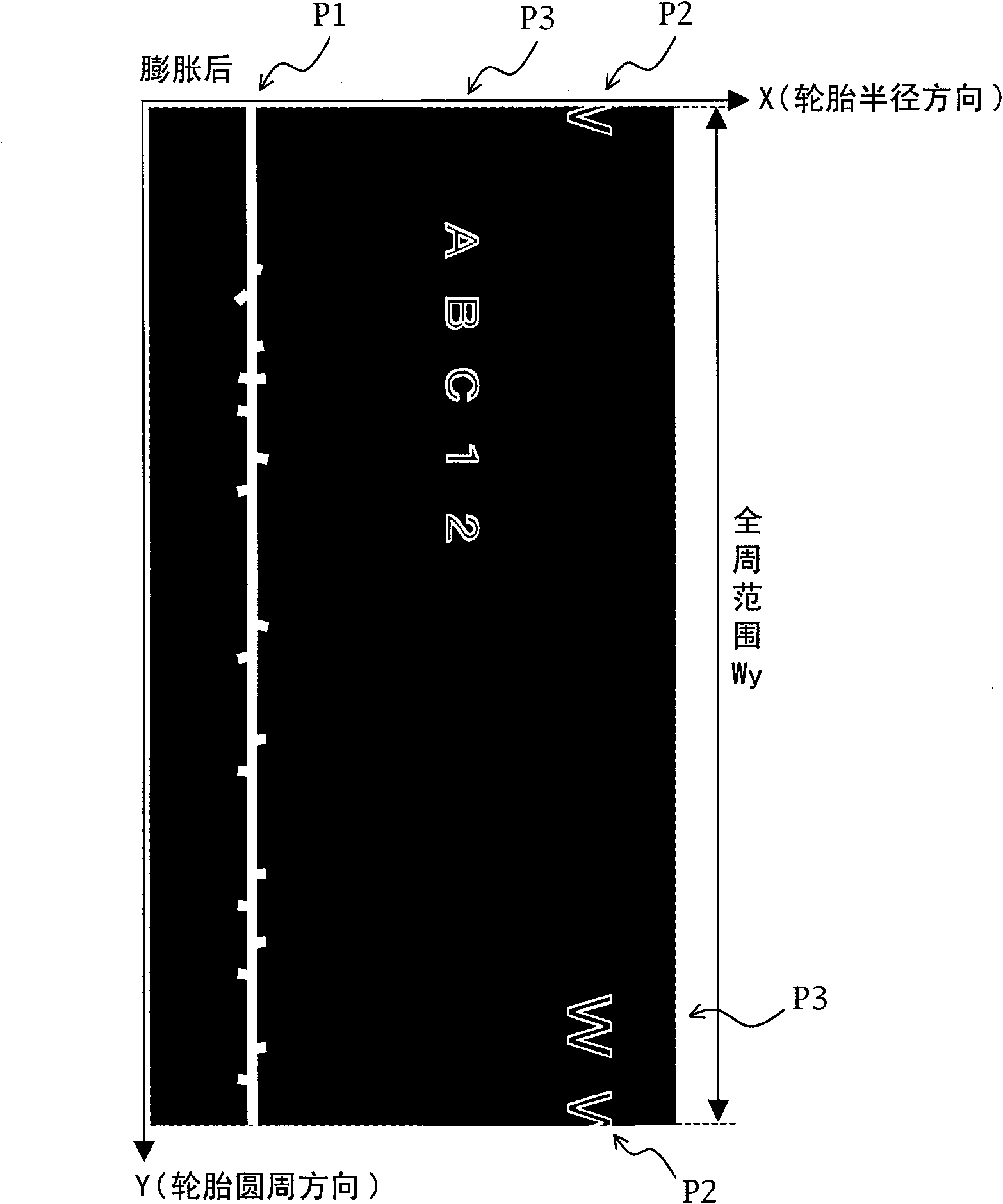
[0168] The tire shape inspection device W of the first invention uses a camera to capture an image of the line light irradiated on the surface of the rotating tire 1, and detects the shape by the optical section method based on the captured image, thereby measuring the height distribution of the tire 1 surface, and performing shape inspection. Assay processing. Through this shape measurement process, surface height distribution information showing the distribution of the measured su...


PUM


Abstract

Disclosed is a tire shape inspection method that can reliably and without misidentification perform accurate shape defect inspection in a short period of time by excluding measurement values in a range in which embossed marks are formed from distribution information for surface height measurement values on the sidewall surface of a tire. In the method, a processor automatically detects the positions of the embossed marks based on sample surface shape information obtained from a sample of the tire, and automatically sets coordinate information for a mask range surrounding the area where said marks are present (S2-S15). The processor also causes a surface shape image based on the sample surface shape information and a mask range image based on the coordinate information for the mask range to be displayed superimposed on a display means, and changes the coordinate information for the mask range according to an operating input (S16). The processor also corrects deviation in the coordinatesystem between the surface height distribution information obtained from the tire undergoing inspection and the coordinate information for the mask range after changing, and excludes measurement values in the mask range from shape defect inspection processing.

Description

technical field [0001] The present invention relates to a tire shape inspection method and a device thereof for inspecting a shape defect of a side wall of a tire on which uneven marks are formed. Background technique [0002] A tire has a structure in which various materials such as rubber, chemical fibers, and steel cords are laminated. If there is an uneven part in the laminated structure, when inflated, the part with relatively weak pressure resistance will have a raised part (protrusion) called a bulge or a dent or a depression ( depression) of the sunken part (concave). Tires having shape defects such as bulges and dents require inspection and are excluded from shipping because of problems in safety or poor appearance. [0003] Usually, when inspecting the shape of a tire, first, the tire is rotated and driven with a rotating machine in a state where a predetermined displacement sensor is placed facing the tire surface (sidewall surface or tread). [0004] For examp...

Claims


Application Information

Patent Timeline
IPC IPC(8): G01B11/24B60C19/00G01B11/30
CPCG06T7/0004G01B11/25G06T2207/10028G06T7/521
Inventor 高桥英二迫田尚和
Owner KOBE STEEL LTD
Why Eureka
Try Eureka