Robot arm part

一种机器人臂、部件的技术,应用在爪臂、机械手、机械设备等方向,能够解决体积庞大、不便安装、结构复杂等问题,达到体积小、便于安装、传动平稳的效果

Inactive Publication Date: 2011-06-08
HONG FU JIN PRECISION IND (SHENZHEN) CO LTD +1
View PDF6 Cites 22 Cited by
  • Summary
  • Abstract
  • Description
  • Claims
  • Application Information

AI Technical Summary

Problems solved by technology

Therefore, when using a motor for driving, it is necessary to use a reduction device with a large reduction ratio to reduce the speed. In order to achieve the reduction ratio requirement, if an ordinary reducer is used, it needs to be realized through multi-stage reduction, resulting in complex structure, large volume, and inconvenient installation.

Method used


Image

  • Robot arm part
  • Robot arm part
  • Robot arm part

Examples


Embodiment Construction

[0012] The robot arm component of the present invention will be further described in detail below in conjunction with the accompanying drawings and specific embodiments.

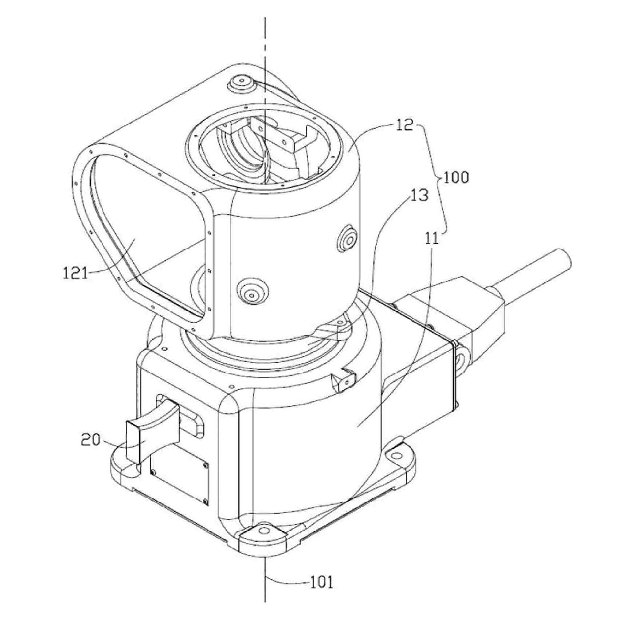
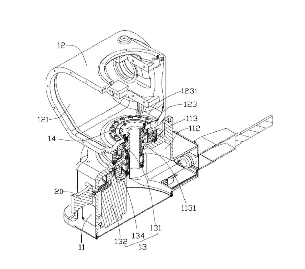
[0013] see figure 1 and figure 2 , the robot arm part 100 according to the embodiment of the present invention includes a first hollow arm part 11 , a second hollow arm part 12 and a connection joint 13 connecting the first hollow arm part 11 and the second hollow arm part 12 . The second hollow arm part 12 is rotatable relative to the first hollow arm part 11 about the rotation axis 101 . The robot arm part 100 of this embodiment can be applied to a rotating structure of a six-axis robot near its base portion.

[0014] Both the first hollow arm portion 11 and the second hollow arm portion 12 are substantially cylindrical shells, and respectively have a first hollow portion 112 and a second hollow portion 121 . The first hollow arm portion 11 includes a first installation wall 113 , and the second hollow...


PUM


Abstract

The invention provides a robot arm part which comprises a first hollow arm part, a second hollow arm part and a connecting joint used for connecting the first hollow arm part with the second hollow arm part, wherein the connecting joint comprises a driver with an output shaft, a harmonic wave retarding mechanism and a belt transmission mechanism, wherein the harmonic wave retarding mechanism comprises a wave generator, a flexible wheel arranged outside the wave generator, and a rigid wheel arranged outside the flexible wheel and meshed with the flexible wheel; the flexible wheel is relativelyfixed with the first hollow arm part, and the rigid wheel is relatively fixed with the second hollow arm part; and the belt transmission mechanism comprises a drive belt wheel, a driven belt wheel and a transmission belt, the drive belt wheel is fixedly connected with the output shaft of the driver, and the driven belt wheel is relatively fixed with the wave generator to drive the wave generator to rotate around a rotating axis. The robot arm part can obtain larger retarding ratio, has a compact structure, and is convenient for installation.

Description

technical field [0001] The invention relates to a robotic arm component. Background technique [0002] A robot generally includes a base and a plurality of arm parts connected in sequence, and each arm part can rotate around a rotation axis so that the robot can obtain a required degree of freedom. When the arm part of the robot, especially the arm part close to the base, rotates, its moment of inertia is generally large, and its overload capacity and impact resistance are restricted, so the rotational speed is required not to be too high. Therefore, when using a motor for driving, it is necessary to use a reduction device with a large reduction ratio to reduce the speed. In order to achieve the reduction ratio requirement, if an ordinary reducer is used, it needs to be realized through multi-stage reduction, resulting in complex structure, large volume, and inconvenient installation. . Contents of the invention [0003] In view of the above situation, it is necessary to...

Claims


Application Information

Patent Timeline
Patent Type & Authority Applications(China)
IPC IPC(8): B25J18/00
CPCB25J9/1025Y10T74/20323
Inventor 郜东伟刘振星
Owner HONG FU JIN PRECISION IND (SHENZHEN) CO LTD
Why Eureka
Try Eureka