Exhaust heat recovery system of vehicle and method thereof

A technology of exhaust heat and recovery method, applied in vehicle components, exhaust devices, engine cooling, etc., can solve problems such as increasing vehicle manufacturing costs, and achieve the goal of reducing oil friction, rapidly increasing temperature, and reducing fuel consumption. Effect

Inactive Publication Date: 2011-06-08
HYUNDAI MOTOR CO LTD +1
View PDF4 Cites 14 Cited by
  • Summary
  • Abstract
  • Description
  • Claims
  • Application Information

AI Technical Summary

Problems solved by technology

[0005] As catalyst loading increases and Exhaust Gas Recirculation (EGR) cooler capacity becomes larger for exhaust gas conditioning, it also increases vehicle manufacturing costs

Method used


Image

  • Exhaust heat recovery system of vehicle and method thereof
  • Exhaust heat recovery system of vehicle and method thereof
  • Exhaust heat recovery system of vehicle and method thereof

Examples


Embodiment Construction

[0025] Reference will now be made in detail to various embodiments of the invention, examples of which are illustrated in the accompanying drawings and described below. While the invention will be described in conjunction with exemplary embodiments, it will be understood that that description is not intended to limit the invention to those exemplary embodiments. On the contrary, the invention is intended to cover not only the exemplary embodiments, but also various alternatives, modifications, equivalent constructions and other embodiments, which may be included within the spirit and scope of the invention as defined by the appended claims.

[0026] In the following detailed description, there are shown and described certain exemplary embodiments of the present invention, simply by way of illustration.

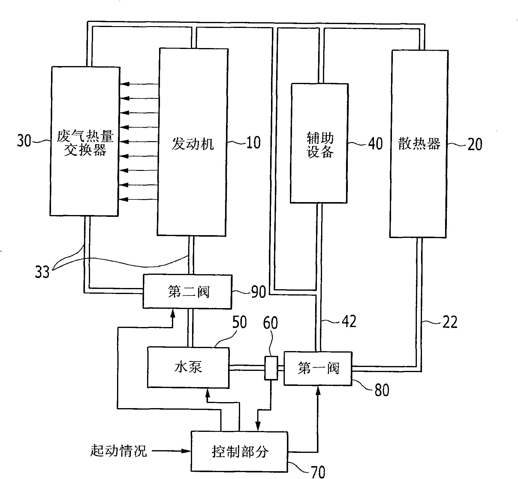
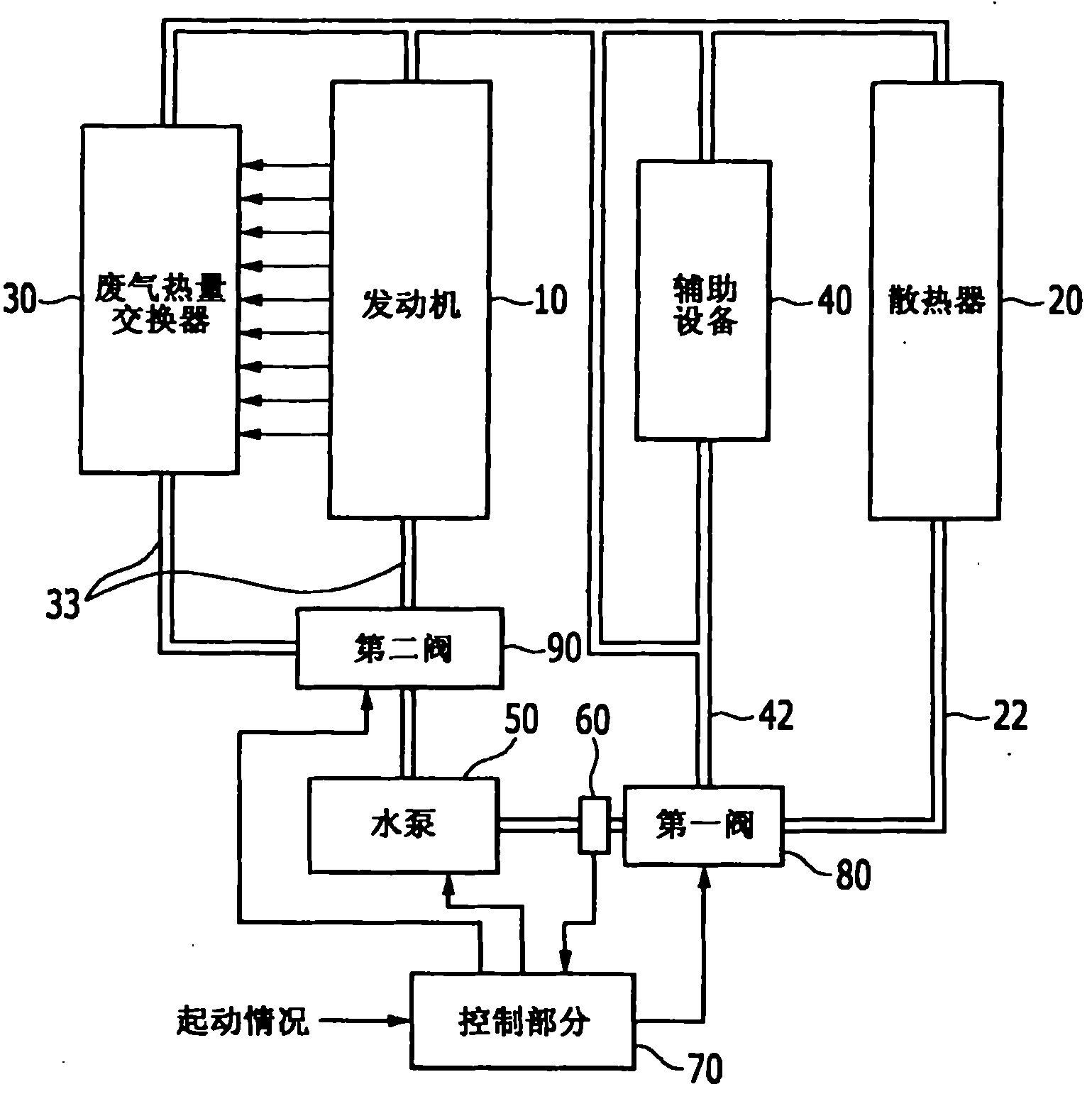
[0027] figure 1 An exhaust gas heat recovery device of a vehicle according to an exemplary embodiment of the present invention is schematically shown.

[0028] The present i...


PUM


Abstract

The present invention relates to an exhaust heat recovery system of a vehicle and a method thereof, wherein an exhaust heat recovery device may include a radiator disposed at a main line and through which hot coolant circulates; an exhaust heat exchanger transferring exhaust heat of an engine to coolant; a first valve selectively circulating the coolant to the main line or a bypass line; a water pump connected to the first valve and circulating the coolant; a coolant temperature sensor detecting temperature of the coolant; a second valve connected to the water pump and disposed at a distributing line to distribute the coolant supplied by the water pump to the engine and the exhaust heat exchanger; and a control portion that controls the first and second valves depending on the temperature of the coolant so as to adjust coolant amount circulating in the engine and the exhaust heat exchanger and coolant amount circulating in the radiator and the bypass line.

Description

[0001] Cross References to Related Applications [0002] This application claims priority from Korean Patent Application No. 10-2009-0118730 filed in the Korean Intellectual Property Office on December 2, 2009, the entire contents of which are hereby incorporated by reference for all purposes. technical field [0003] The invention relates to an exhaust heat recovery device for vehicles. More particularly, the present invention relates to an exhaust heat recovery device for recovering exhaust heat to reduce fuel consumption, and an exhaust heat recovery method. Background technique [0004] In general, vehicle manufacturers are researching ways to reduce exhaust emissions and fuel consumption. [0005] As catalyst loading increases and Exhaust Gas Recirculation (EGR) cooler capacity becomes larger to accommodate exhaust gas conditioning, vehicle manufacturing costs also increase. [0006] A variable water pump prevents unnecessary cooling, reducing engine warm-up time and ...

Claims


Application Information

Patent Timeline
Patent Type & Authority Applications(China)
IPC IPC(8): F01N5/02F01P7/16B60K11/04
CPCY02T10/16F01P7/165F01P7/16F01P2060/08F01N5/02Y02T10/12F02G5/02
Inventor 黄淳炫李凤相
Owner HYUNDAI MOTOR CO LTD
Why Eureka
Try Eureka