X-ray system with efficient anode heat dissipation

An X-ray and anode technology, applied in X-ray tubes, components of X-ray tubes, cathode ray convergence/focusing/guiding, etc.

Inactive Publication Date: 2011-06-08
KONINK PHILIPS ELECTRONICS NV
View PDF7 Cites 11 Cited by
  • Summary
  • Abstract
  • Description
  • Claims
  • Application Information

AI Technical Summary

Problems solved by technology

But even miniaturized x-ray sources face the aforementioned thermal problems

Method used


Image

  • X-ray system with efficient anode heat dissipation
  • X-ray system with efficient anode heat dissipation
  • X-ray system with efficient anode heat dissipation

Examples


Embodiment Construction

[0045] Hereinafter, the X-ray scanning system according to an exemplary embodiment of the present invention will be described in more detail according to specific improvements and with reference to the accompanying drawings.

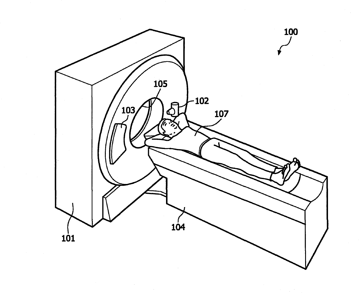
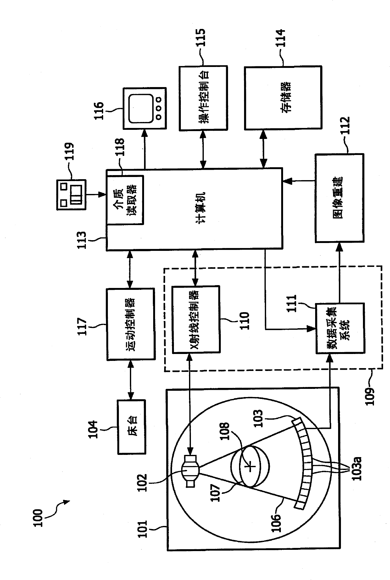
[0046] Figure 1a The structure of a known art CT imaging system is shown. in such as Figure 1a In the described conventional CT imaging system, an x-ray source 102 mounted on a rotating gantry 101 rotates about a longitudinal axis 108 of a patient's body 107 or any other object to be examined while simultaneously producing a fan-shaped or cone-shaped x-ray beam 106 . The X-ray detector array 103 is usually installed on the frame 101 diametrically opposite to the position of the X-ray source 102, and the X-ray detector array rotates in the same direction around the patient's longitudinal axis 108, and simultaneously detects The attenuated X-rays that pass through the patient's body 107 are converted into electrical signals. The image rendering and rec...


PUM


Abstract

X-ray systems for use in high-resolution imaging applications with an improved power rating are provided. An X-ray source comprises at least one integrated actuator unit (206, 206', 206a or 206b) for performing at least one translational and / or rotational displacement by moving the position of the X-ray source's anode (204, 204', 204a' or 204b') relative to a stationary reference position. This helps to overcome power limitations due to an overheating of the anode at its focal spot position (205). In addition to that, a focusing unit (203) for allowing an adapted focusing of the anode's focal spot (205) which compensates deviations in the focal spot size resulting from said anode displacements and / or a deflection means (211, 21 Ia or 21 Ib) for generating an electric and / or magnetic field deflecting the electron beam (202, 202a or 202b) in a direction opposite to the direction of the rotary anode's displacement movement may be provided.

Description

technical field [0001] The present invention relates to x-ray systems with enhanced power ratings for high resolution imaging applications, and more particularly to various system configurations for x-ray based image acquisition systems using rotating anode type x-ray sources, or Instead an array of spatially distributed X-ray sources fabricated in carbon nanotube (CNT) technology is used, thus allowing higher sampling rates to enable the Acquire CT images with enhanced temporal resolution. According to the invention, each X-ray source comprises at least one integrated actuator unit for at least one translational and / or rotational displacement by moving the anode position of the X-ray source relative to a fixed reference position, which may be, for example, Given by the mounting plate or electron beam emitting cathode providing the electron beam impinging on said anode. In addition, a focusing unit and / or a deflection device may be provided, the focusing unit is used to adju...

Claims


Application Information

Patent Timeline
Patent Type & Authority Applications(China)
IPC IPC(8): A61B6/03H01J35/24
CPCA61B6/4021A61B6/4085A61B6/4028H01J35/14H01J35/26A61B6/032A61B6/4488H01J35/30H01J35/28H01J35/147H01J35/153
Inventor G·福格特米尔R·皮蒂格A·莱瓦尔特R·K·O·贝林
Owner KONINK PHILIPS ELECTRONICS NV
Why Eureka
Try Eureka