
Airflow atomizer

An atomizer and air-flow technology, which is applied in the direction of injection devices and liquid injection devices, can solve the problems of poor product particle size uniformity and insufficient atomization ability, and achieve the effects of reducing energy consumption, simple structure, and improving production capacity

Inactive Publication Date: 2011-06-15
CHANGZHOU LEMAR DRYING ENG
View PDF5 Cites 13 Cited by
  • Summary
  • Abstract
  • Description
  • Claims
  • Application Information

AI Technical Summary

Problems solved by technology

Although air-flow atomization can atomize higher-viscosity material liquids compared with centrifugal spray and pressure spray, when air-flow spray drying processes certain liquids with poor fluidity, high viscosity, and filiform splitting, if the spray gun mist The chemical ability is not strong enough, and the filaments in the filiform division are not easy to break, resulting in poor particle size uniformity of the product

Method used


Image

  • Airflow atomizer
  • Airflow atomizer
  • Airflow atomizer

Examples


Embodiment 1

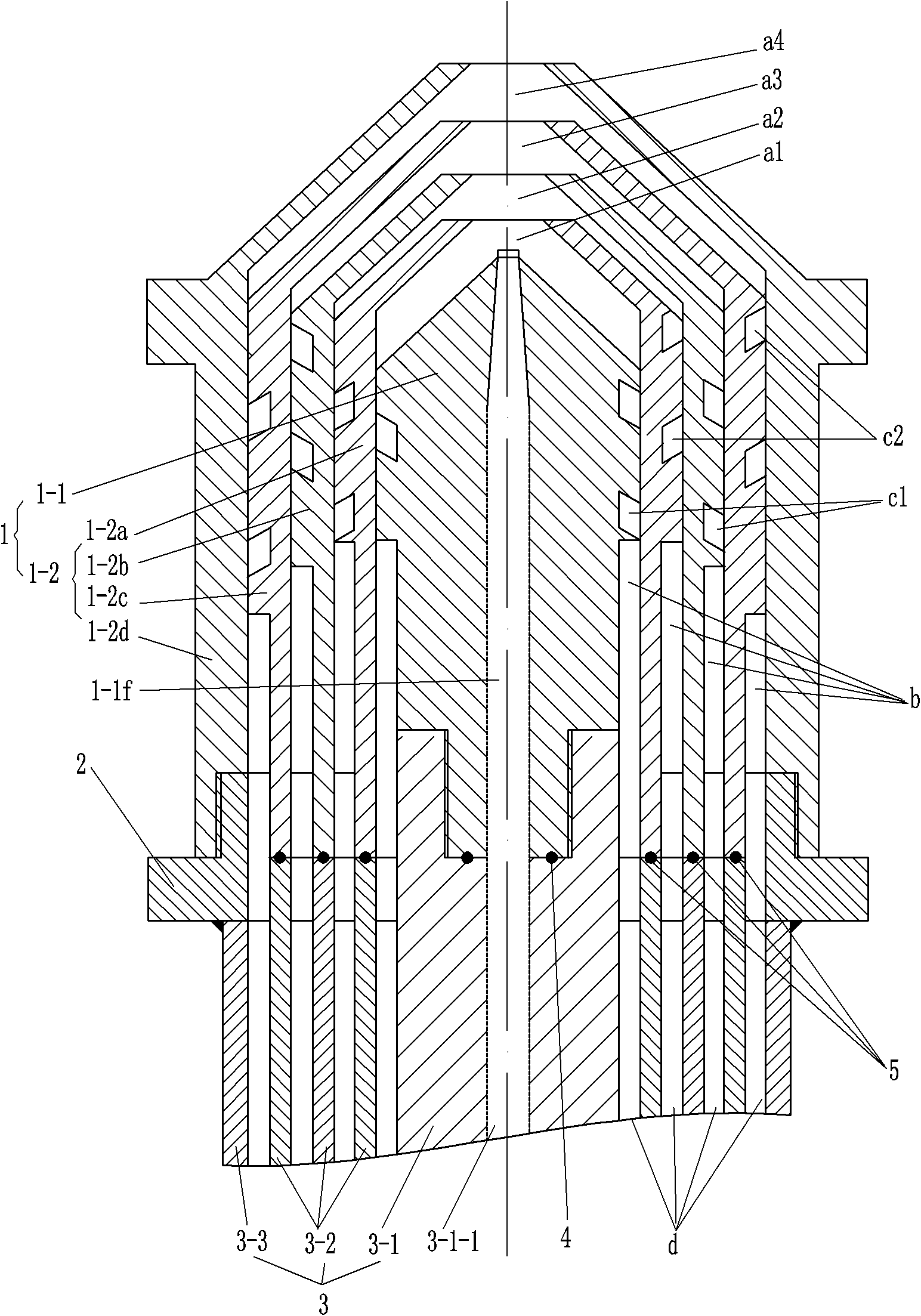
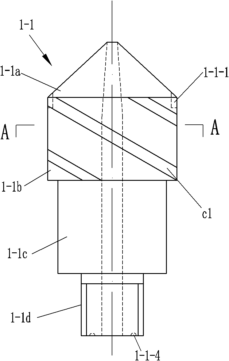
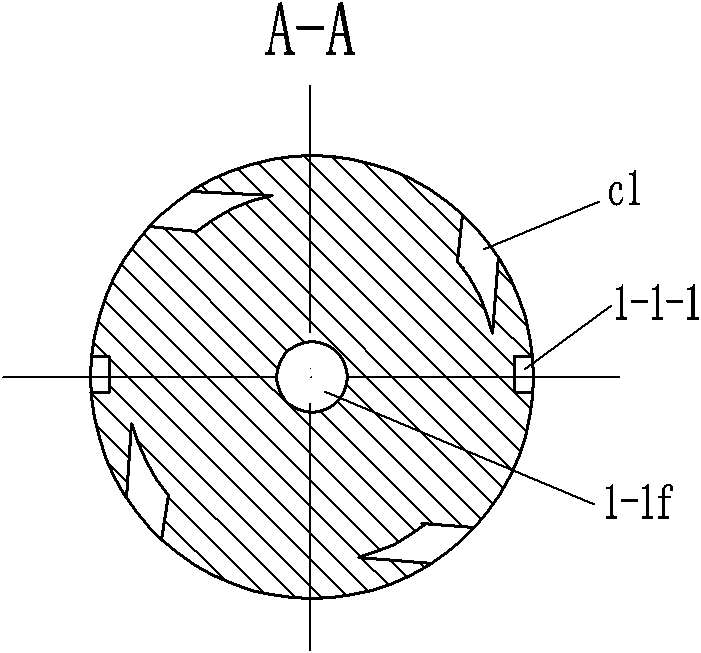
[0028] see Figure 1 to Figure 11 , This embodiment includes a spray gun 1, a hollow connecting seat 2 and a support tube 3. The spray gun 1 has five overlapping nozzles, the middle nozzle is the liquid nozzle 1-1, and the other four nozzles are the gas nozzle 1-2. The gas nozzle 1-2 includes a first gas nozzle 1-2a, a second gas nozzle 1-2b, a third gas nozzle 1-2c, a fourth gas nozzle 1-2d, and a fourth gas nozzle 1-2d from the inside to the outside. It is the gas nozzle at the outermost layer, and at the same time plays the role of the shell. The support tube 2 is connected with the outermost gas nozzle of the spray gun 1, that is, the fourth gas nozzle 1-2 d by the hollow connecting seat 2.

[0029] The material liquid nozzle 1-1 includes a tapered head 1-1a and a cylinder, and the material liquid nozzle 1-1 is provided with a material liquid hole 1-1f. The gas nozzle 1-2 includes a tapered head and a cylinder. The inner cavity of the conical head 1-2a-a of the first gas n...

Embodiment 2

[0038] see Figure 12 to 14 , Example 2 has 4 nozzles stacked one on top of the other, the middle nozzle is the liquid nozzle 1-1, and the other 3 nozzles are the gas nozzle 1-2. The gas nozzle 1-2 includes a first gas nozzle 1-2a, a second gas nozzle 1-2e, and an outermost gas nozzle 1-2d from the inside to the outside, and the spiral grooves on two adjacent nozzles rotate in opposite directions. Compared with Embodiment 1, there is one less gas nozzle, and the gap of the second gas nozzle 1-2e is an annular gap, and other structures are the same as Embodiment 1.


PUM


Abstract

The invention discloses an airflow atomizer, which comprises a spray gun and a supporting pipe, wherein the spray gun is provided with at least four superposed nozzles, the nozzle in the center is a liquid nozzle which is provided with a liquid hole, the other nozzles are gas nozzles, the front part of the cavity of each gas nozzle is an atomization area, the lower part of the column of the liquid nozzle is inwards shrunk to form an annular clearance, and the lower parts of the columns of the other gas nozzles except the outermost gas nozzle are inwards shrunk to form annular clearances; the outer wall of the upper part of the column of the liquid nozzle is provided with a plurality of uniformly distributed spiral grooves passing through the front atomization area and the rear annular clearance, and the outer walls of the upper parts of the columns of the other gas nozzles except the outermost gas nozzle are provided with a plurality of uniformly distributed spiral grooves passing through the front atomization areas and the rear annular clearances respectively; and the spiral directions of the spiral grooves on the inner and outer adjacent nozzles are opposite. The airflow atomizer has strong atomization capacity, and can adapt to the atomization of silk-like split liquid with poor mobility and high viscosity.

Description

Technical field [0001] The invention relates to an airflow atomizer used in a spray dryer. Background technique [0002] The working principle of the airflow atomizer is to use high-speed airflow to split the liquid film, and the high-speed airflow can use compressed air. When compressed air is ejected from the atomizer at a high annular velocity, the flow rate of the material and liquid is very low, so there is a large relative speed difference between the two, and friction and shear forces are generated between the gas and the liquid, so The feed liquid forms fine droplets. The Chinese patent number is 00240918.6. The utility model patent specification discloses a spray drying granulator. The atomizer spray gun is a three-flow spray gun. It consists of a liquid material tube in a support tube and a liquid spray nozzle. A channel, a primary compressed air channel composed of a primary compressed air pipe and a primary compressed air nozzle, and a secondary compressed air chan...

Claims


Application Information

Patent Timeline
IPC IPC(8): B05B7/04B05B7/02
Inventor 周友来徐德兵
Owner CHANGZHOU LEMAR DRYING ENG
Learn More