A self-driven flotation device for ore pulp with high-pressure jet stirring function

A high-pressure jet and flotation device technology, applied in flotation, solid separation, etc., can solve the problems of excessive turbulence in the flow field, large maintenance, and affect the flotation effect, and achieve the effect of rapid mixing and high-efficiency flotation

Active Publication Date: 2019-04-05
ANHUI UNIV OF SCI & TECH
View PDF8 Cites 0 Cited by
  • Summary
  • Abstract
  • Description
  • Claims
  • Application Information

AI Technical Summary

Problems solved by technology

The mechanical agitation flotation machine has been used for the longest time. It has a history of nearly a hundred years from ore dressing to coal dressing. It can provide a turbulent environment for the flotation tank, but the disadvantages are high energy consumption and large maintenance
The non-mechanical stirring flotation machine, also known as the inflatable flotation machine, uses a pump to provide energy for the pulp, and absorbs enough air through the jet flow and collision of the pulp. The disadvantage is that it needs a matching pump and consumes a lot of energy.
At the same time, because the non-mechanical agitation flotation machine needs to ensure sufficient ore flow and suction volume, the flow field in the flotation tank is often excessively turbulent, which will cause the mineralized particles to fall off during the flotation process, thereby affecting the flotation process. selection effect

Method used


Image

  • A self-driven flotation device for ore pulp with high-pressure jet stirring function
  • A self-driven flotation device for ore pulp with high-pressure jet stirring function
  • A self-driven flotation device for ore pulp with high-pressure jet stirring function

Examples


Embodiment Construction

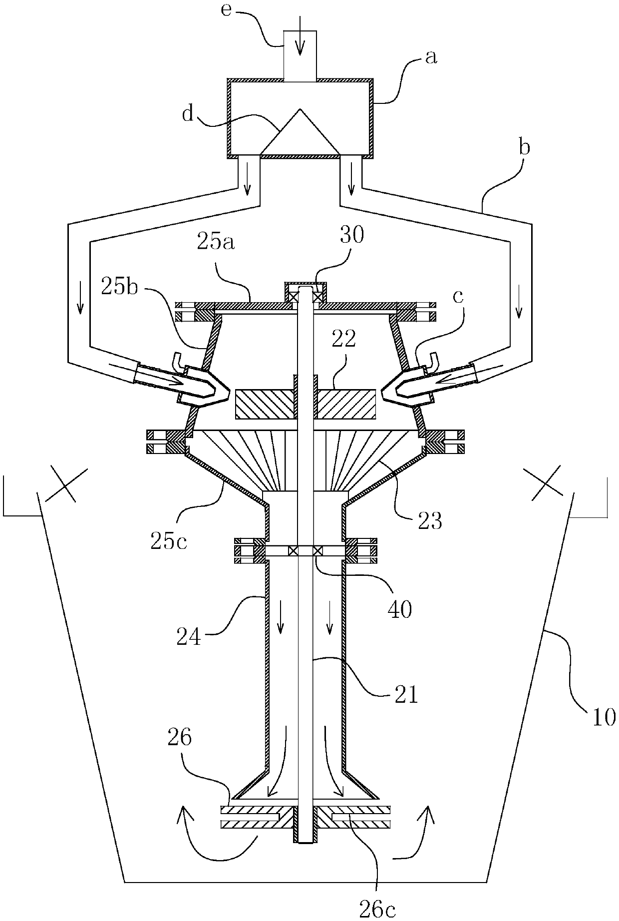
[0032] For ease of understanding, combined here Figure 1-5 , the specific embodiments of the present invention are further described as follows:

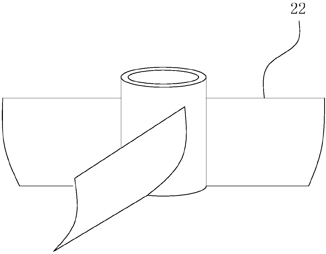
[0033] The detailed components of the present invention are divided into several modules, including: the flotation cell 10, the split flow assembly, the high-pressure injection assembly and the lower stirring assembly, which are described one by one below:

[0034] 1. Flotation cell

[0035] As a conventional flotation device, the flotation cell 10 can be equipped with auxiliary flotation operation structures such as bubble scraping mechanism, etc., so as to realize its inherent flotation function.

[0036] 2. Shunt component

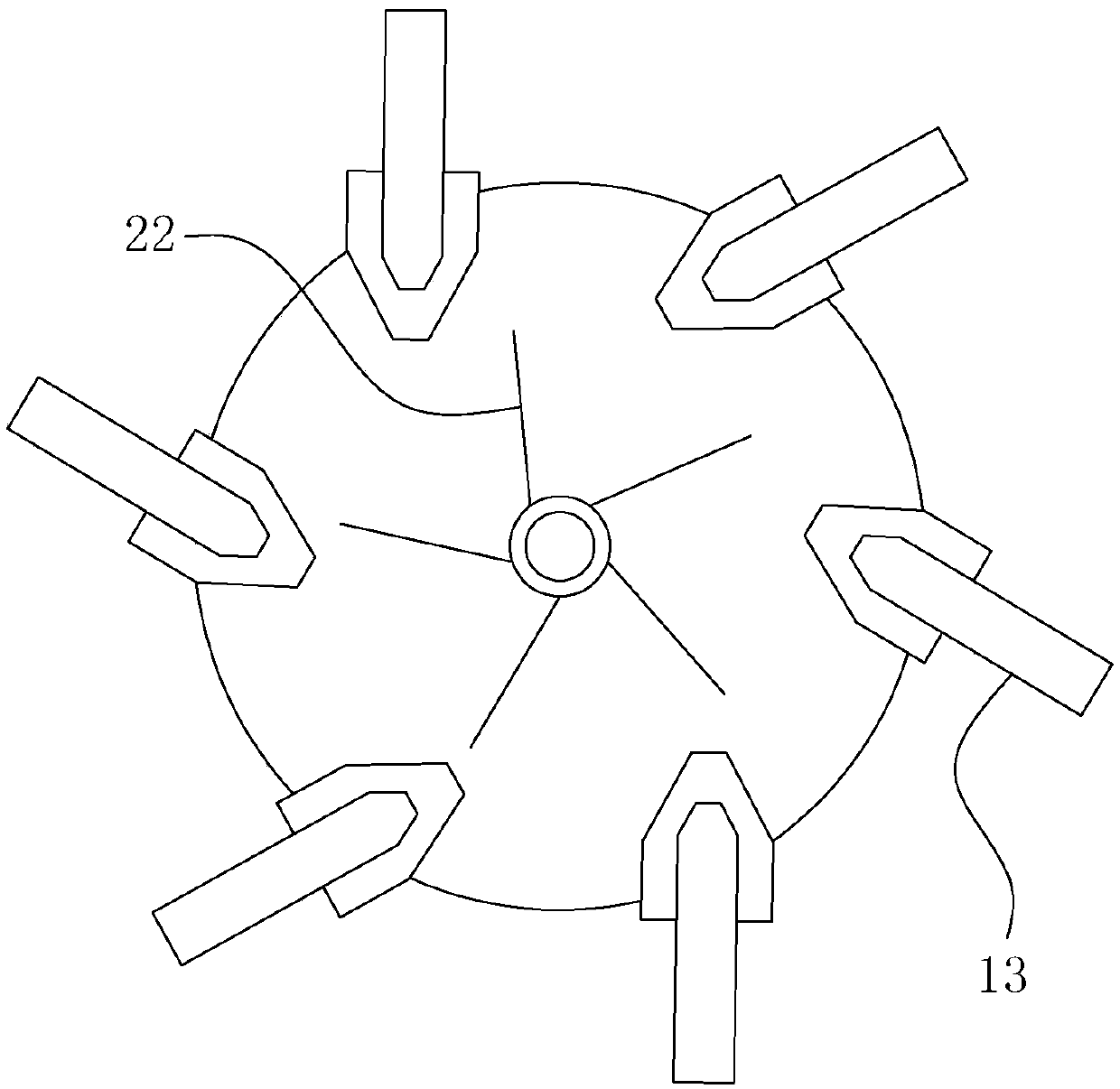
[0037] shunt components to Figure 1-2 When the structure shown is a specific embodiment, it is mainly subdivided into a sextant and an injection port c at the end of the branch pipe b connected to the sextant.

[0038] The sextant, as the main part of the diversion assembly, is set up to divide the flotat...


PUM


Abstract

The invention relates to the field of coal slime pulp-mixing flotation treatment, in particular to an ore-pulp self-driving-type flotation device with a high-pressure jet-flow stirring function. The device comprises a flotation tank, a stirring part is arranged in the flotation tank and comprises a high-pressure cavity, a rotating shaft is vertically arranged in the high-pressure cavity in the axial vertical direction, and an upper driving wheel is fixed on the rotating shaft; jet orifices are formed in the circumferential direction of the high-pressure cavity, the outlet ends of the jet orifices point to the position of the paddle surface of the upper driving wheel, and a pulp-mixing retainer is arranged under the upper driving wheel; and a discharging cylinder extending downwards is coaxially located at the bottom end of the high-pressure cavity, an outlet of the lower portion of the pulp-mixing retainer communicates with and points to the feeding end of the discharging cylinder, the stirring part further comprises a lower stirring wheel coaxially fixed at the shaft end of the bottom of the rotating shaft, and a discharging path of the discharging cylinder is located within the wheel blade stirring range of the lower stirring wheel. The ore-pulp self-driving-type flotation device with the high-pressure jet-flow stirring function has the advantages that the energy consumption is low, the maintenance amount is low, and the separation effect is good, the high-efficiency flotation demand of the ore-pulp can be achieved efficiently and controllably, and the early equipment investment of a coal preparation plant can be reduced.

Description

technical field [0001] The invention relates to the field of coal slurry flotation treatment, in particular to a slurry self-driven flotation device with high-pressure jet stirring function. Background technique [0002] The flotation method is the most important interface separation method, and it has been widely used in the fields of separation flotation of polymetallic ores, comprehensive utilization of complex ores, iron ore flotation and non-metallic ore flotation, especially- The only effective sorting method for 0.1mm coal slime. The theoretical basis of various flotation processes is roughly the same, that is, due to the hydrophobic characteristics of the surface of the ore particles or the hydrophobic (air-friendly or oil) characteristics obtained after the action of the flotation agent, the ore particles will be in liquid-gas or water-oil. Agglomeration occurs at the interface. At present, the most widely used method is the froth flotation method, which includes ...

Claims


Application Information

Patent Timeline
Patent Type & Authority Patents(China)
IPC IPC(8): B03D1/16
CPCB03D1/1443B03D1/16
Inventor 朱金波韩有理周伟费之奎王超王海楠朱宏政朱再胜
Owner ANHUI UNIV OF SCI & TECH
Why Eureka
Try Eureka