
Device for cleaning dust deposited in pipeline

A cleaning device and a technology for accumulating dust, which are applied in the directions of cleaning hollow objects, cleaning methods and utensils, chemical instruments and methods, etc., can solve the problems of affecting airflow, blockage, cumbersome links, etc., so as to achieve convenient installation and disassembly, and easy installation and use. , The effect of convenient operation and maintenance

Inactive Publication Date: 2011-06-15
HEFEI CEMENT RES DESIGN INST
View PDF5 Cites 12 Cited by
  • Summary
  • Abstract
  • Description
  • Claims
  • Application Information

AI Technical Summary

Problems solved by technology

[0002] In industrial applications, pipelines are often used to convey dust-laden airflow to improve ventilation or to send away materials; however, in practical applications, often due to the small inclination angle of the pipeline, too long conveying pipeline or too slow airflow velocity, and the gravity of the dust itself The sedimentation effect causes some dust particles to accumulate in the pipeline; if the dust accumulation is not cleaned up in time, there will be more and more, resulting in a decrease in the ventilation area of ​​the pipeline and an increase in resistance, which affects the flow of air flow; in severe cases, it will cause blockage and affect the upstream and downstream equipment. run, causing an accident
After dust accumulation occurs, manual dust removal through openings is often used. The working environment is harsh, the links are cumbersome, and the workload is heavy; the dust that is pulled out needs to be transported and processed again; high
If it is dangerous gas or dust, it will cause gas or dust leakage, resulting in personal injury or even accident

Method used


Image

  • Device for cleaning dust deposited in pipeline
  • Device for cleaning dust deposited in pipeline
  • Device for cleaning dust deposited in pipeline

Examples


Embodiment Construction

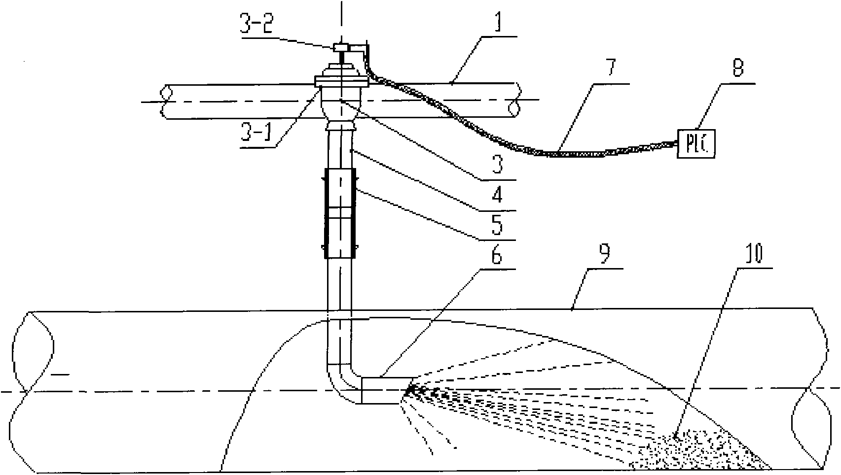
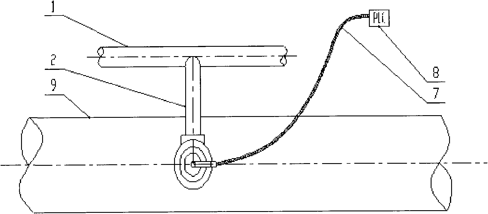
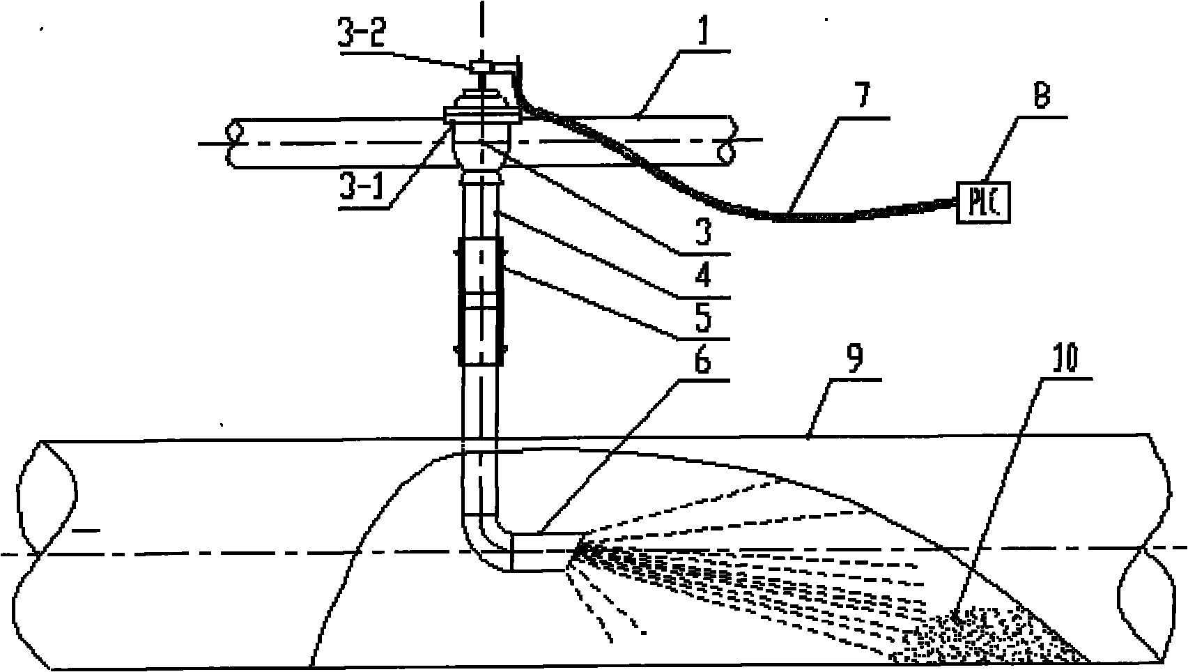
[0014] A pipeline dust cleaning device, including a plurality of blowing pipes 6 fixedly installed on the air flow pipe 9 with the dust 10, the blowing pipe 6 is composed of a straight pipe, a 90° elbow, and a nozzle with a cut angle. The end extends out of the airflow pipe and is connected to the blowing branch pipe 4 through a high-pressure hose 5 with a clamp. The other end of the blowing branch pipe 4 is connected to the pulse valve 3-1 of the electromagnetic pulse valve 3, and the pulse valve 3 -1 is also connected to the air supply branch pipe 2, and the solenoid valve 3-2 of the electromagnetic pulse valve 3 is connected to the controller 8 through the control cable 7; the center line of the nozzle of the blowing pipe 6 and the center line of the air flow pipe 9 coincide.

[0015] When dust 10 appears in the airflow pipe 9, the solenoid valve 32 on the electromagnetic pulse valve 3 can be activated by the controller 8, and the pulse valve 3-1 is opened, and compressed gas i...


PUM


Abstract

The invention discloses a device for cleaning dust deposited in a pipeline. A plurality of blowing pipes are fixedly mounted on an airflow pipeline, one end of each blowing pipe is extended out of the airflow pipeline, and the extended end of each blowing pipe is communicated with a blowing branch pipe through a high-pressure hose, the other end of the blowing branch pipe is communicated with the pulse valve of an electromagnetic pulse valve, the pulse valve is also communicated with an air supply branch pipe, the air supply branch pipe is communicated with an air supply pipeline, and an electromagnetic valve is mounted on the pulse valve and is connected with a controller through a control cable. The device provided by the invention has a simple structure and is convenient to install and use, and can impact deposited soot and raise and carry away dust through the instantaneous expansion of compressed air, so as to avoid the normal movement of dust gas in the pipeline due to the dust. In addition, the device has the advantages of low energy consumption and low cost, and is convenient in operation and maintenance.

Description

Technical field [0001] The invention mainly relates to a device for treating dust accumulation in industrial dust-bearing airflow pipelines, in particular to a pipeline dust accumulation cleaning device. Background technique [0002] In industrial applications, pipes are often used to transport dust-laden airflow to improve ventilation or carry away materials; however, in practical applications, it is often due to the inclination of the pipe being too small, the conveying pipe being too long, or the airflow velocity being too slow, and the gravity of the dust itself Sedimentation causes some dust particles to accumulate in the pipeline; if the dust accumulation is not cleaned up in time, it will increase, resulting in a reduction in the ventilation area of ​​the pipeline, an increase in resistance, and an impact on the flow of air; in severe cases, it will cause blockage and affect upstream and downstream equipment. Operation, causing an accident. After the dust accumulation occ...

Claims


Application Information

Patent Timeline
IPC IPC(8): B08B9/032
Inventor 石峻蔡纯志盛向东储兆洋钮乐怡
Owner HEFEI CEMENT RES DESIGN INST
Learn More