Tool for milling plane of steering knuckle arm
A steering knuckle arm and tooling technology, which is applied to the details of milling machine equipment, positioning devices, milling machine equipment, etc., can solve the problems of low milling machine processing efficiency, inaccurate steering knuckle arm positioning, and unreasonable structure, so as to achieve easy workpiece and avoid machining. The effect of high waste and high processing efficiency
Inactive Publication Date: 2011-06-15
WUHU XINDA FORGING
View PDF0 Cites 6 Cited by
- Summary
- Abstract
- Description
- Claims
- Application Information
AI Technical Summary
Problems solved by technology
Due to the irregular structure of the steering knuckle arm, it is extremely difficult to process it on the milling machine. Therefore, corresponding tooling is generally required. However, the structure of the traditional tooling setting is unreasonable, resulting in inaccurate positioning of the steering knuckle arm. , not in place, difficult to adjust, low efficiency of milling machine processing
Method used
View moreImage
Smart ImageViewing Examples

Examples
Embodiment Construction
Login to View More PUM
 Abstract
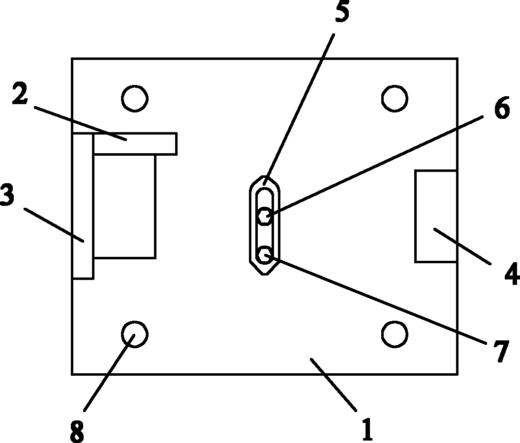
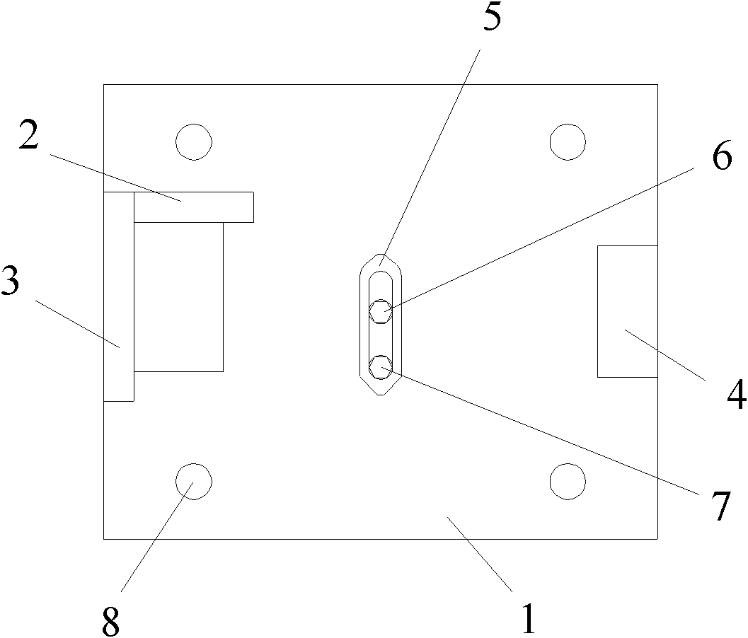
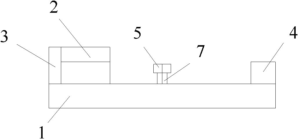
The invention discloses a tool for milling the plane of a steering knuckle arm. The jig comprises a bottom plate, and a location assembly mounted on the bottom plate, wherein the location assembly includes a transverse location plate, a vertical location plate, a cushion block, a pressing plate and a stud bolt, wherein the transverse location plate and the vertical location plate are arranged on the left side of the upper end face of the bottom plate; the cushion block is placed on the right side of the upper end face of the bottom plate; the pressing plate is arranged at the middle part of the upper end face of the bottom plate; and the stud bolt acts on the pressing plate; and one end of the stud bolt is fixed on the bottom plate, and the other end of the stud bolt penetrates through the pressing plate to tightly press the pressing plate through a nut. Through the new design, the tool for milling the plane of a steering knuckle arm can effectively limit the degree of freedom in the X, Y and Z directions of a workpiece through the transverse location plate, the vertical location plate, the pressing plate and the like additionally arranged on the bottom plate of the tool. The tool is in accurate in location and simple in operation, and is convenient in clamping and is easy in adjusting the workpiece. In addition, the milling machine has high processing efficiency, can effectively obviate the production of rejects, and can be widely used in the milling processing of various kinds of steering knuckle arms.
Description
A Tooling for Milling the Plane of Steering Knuckle Arm technical field The invention relates to post-processing equipment of a steering knuckle arm, in particular to a tooling for milling the plane of a steering knuckle arm. Background technique Due to the irregular structure of the steering knuckle arm, it is extremely difficult to process it on the milling machine. Therefore, corresponding tooling is generally required. However, the structure of the traditional tooling setting is unreasonable, resulting in inaccurate positioning of the steering knuckle arm. , not in place, not easy to adjust, and the efficiency of milling machine processing is low. Contents of the invention The technical problem to be solved by the present invention is to provide a tool for milling the plane of the steering knuckle arm in order to overcome the above-mentioned technical defects. In order to solve the technical problems described above, the present invention adopts the following tech...
Claims
Login to View More Application Information
Patent Timeline
 IPC IPC(8): B23Q3/06B23C9/00
Inventor 俞能新余世驹刘争辉陈树金陈月宏张会续
Owner WUHU XINDA FORGING
Features
- R&D
- Intellectual Property
- Life Sciences
- Materials
- Tech Scout
- Unparalleled Data Quality
- Higher Quality Content
- 60% Fewer Hallucinations
Learn More Browse by: Latest US Patents, China's latest patents, Technical Efficacy Thesaurus, Application Domain, Technology Topic, Popular Technical Reports.
© 2025 PatSnap. All rights reserved.Legal|Privacy policy|Modern Slavery Act Transparency Statement|Sitemap|About US| Contact US: help@patsnap.com