Buoyancy type automatic control valve
A buoyancy-type, self-control valve technology, applied to the valve details, valve device, valve operation/release device, etc., can solve the problems of abnormal use, easy failure, high processing precision, etc., and achieve simplified structure, reasonable structure, and high sensitivity high effect
Inactive Publication Date: 2011-06-15
陈银环
View PDF8 Cites 4 Cited by
- Summary
- Abstract
- Description
- Claims
- Application Information
AI Technical Summary
Problems solved by technology
For toilet water storage tanks, the current common solution is to use buoyancy-type self-control valves to control the water level, such as toilet water storage tanks, water towers and other common items. The advantages of using buoyancy-type self-control valves to realize automatic quantitative water supply are: The cost is low, but also because of its many parts, complex structure, and high processing precision requirements, it is prone to failure and cannot be used normally
Method used
View moreImage
Smart ImageViewing Examples

Examples
Embodiment approach
Embodiment 2
Embodiment 3
Login to View More PUM
 Abstract
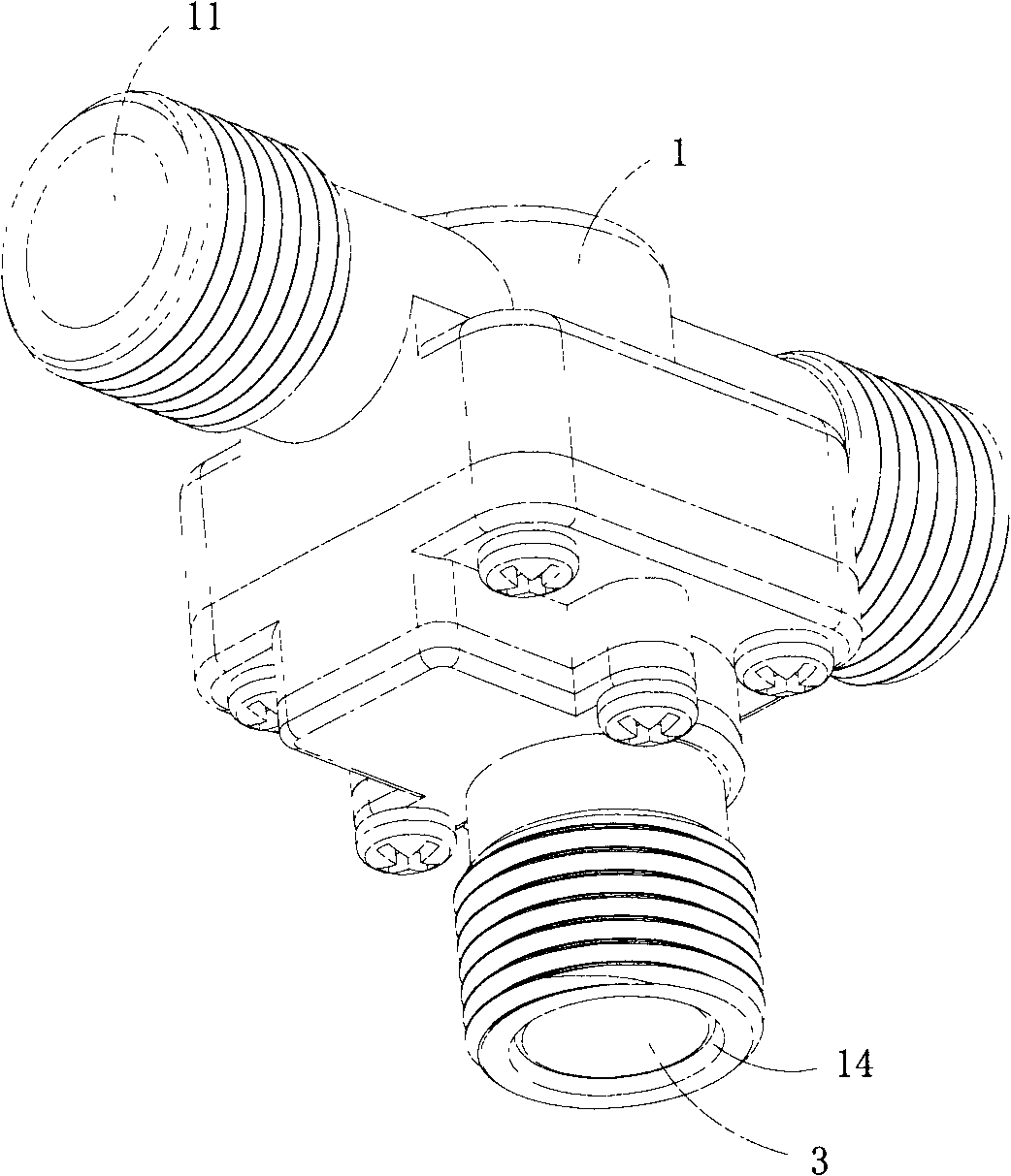
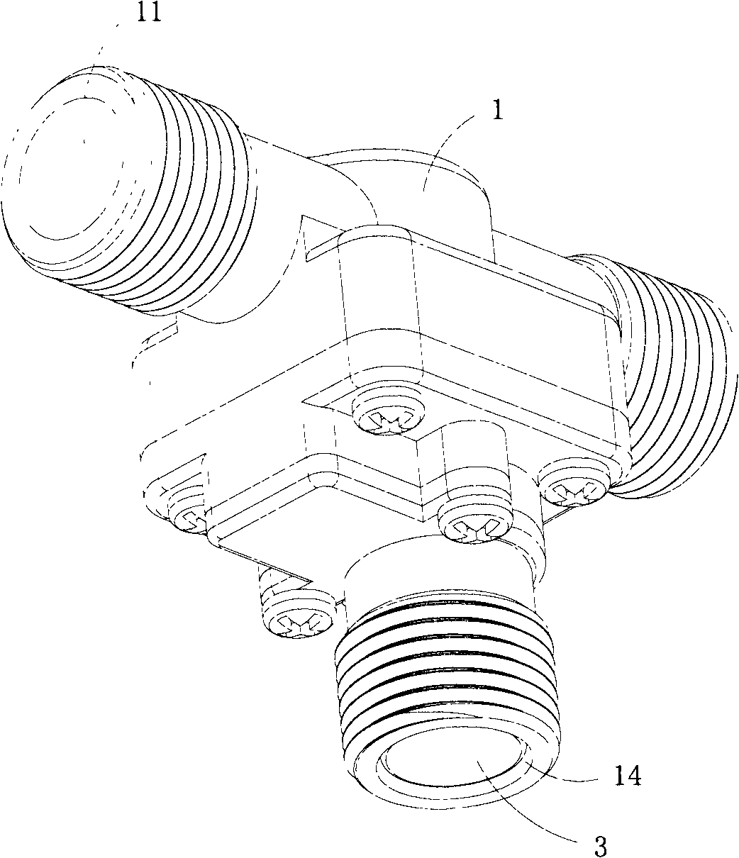
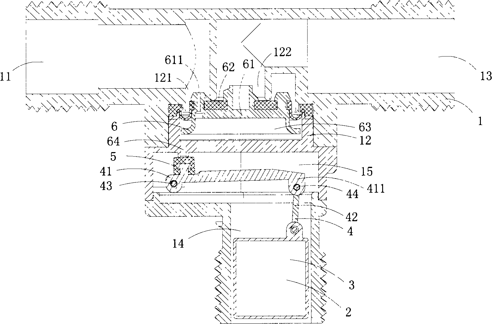
The invention discloses a buoyancy type automatic control valve. The buoyancy type automatic control valve comprises a valve body, a floater, a driving piece, a seal plug and a diaphragm type valve plug assembly; the diaphragm type valve plug assembly comprises a pressure relieving piece, and a seal film arranged on the pressure relieving piece; the valve body comprises a water inlet passage, a pressure regulation chamber and a water outlet passage; a water inlet pipe communicated with the water inlet passage and an water outlet pipe communicated with the water outlet passage are arranged in the pressure regulation chamber; a pressure regulation cavity is formed between one end of the pressure regulation chamber near the floater and the diaphragm type valve plug assembly; a water diversion hole communicated with the pressure regulation cavity and the water inlet passage is formed on the pressure relieving piece; a pressure regulation hole is formed at one end of the pressure regulation chamber near the floater; and the floater drives the seal plug to block up or separate from the pressure regulation hole through the driving piece in the reciprocating process. Water channel in the valve body can be automatically connected or disconnected according to the change of water level in a water storage container without power supply so as to realize automatically supplying water or cutting off the water supply; moreover the buoyancy type automatic control valve has a reasonable and simplified structure and high sensitivity, can guarantee the service life of a floating ball, and is not easily damaged.
Description
A kind of buoyancy automatic control valve technical field The invention belongs to the technical field of structural design of automatic control valves, and in particular relates to a buoyancy type automatic control valve. Background technique Common open water storage containers, such as buckets, pots, vats, water towers, and toilet flushers, have a capacity problem when storing water, that is, when water is added to a certain level, the water will overflow , so certain measures are needed to prevent its overflow. For example, in a restaurant, when chefs cook, they use water very frequently, with a time limit, and the amount is relatively large. Their habitual practice is to put an open container under the faucet, and then turn on the tap all the time. Scooping from an open container will result in a large amount of water draining away. For this approach, there is no corresponding product on the market at present. For toilet water storage tanks, the current common so...
Claims
Login to View More Application Information
Patent Timeline
 Patent Type & Authority Applications(China)
IPC IPC(8): F16K31/34
Inventor 陈银环
Owner 陈银环
Features
- R&D
- Intellectual Property
- Life Sciences
- Materials
- Tech Scout
- Unparalleled Data Quality
- Higher Quality Content
- 60% Fewer Hallucinations
Learn More Browse by: Latest US Patents, China's latest patents, Technical Efficacy Thesaurus, Application Domain, Technology Topic, Popular Technical Reports.
© 2025 PatSnap. All rights reserved.Legal|Privacy policy|Modern Slavery Act Transparency Statement|Sitemap|About US| Contact US: help@patsnap.com