Drier vibrator

A vibrating device and drying machine technology, which is applied in the direction of drying solid materials, drying, lighting and heating equipment, etc., can solve the problems of reduced work efficiency, long drying time, and blockage of wet materials, so as to improve work efficiency and achieve obvious effects Effect

Inactive Publication Date: 2011-06-15
YUZHOU WEILITE CHEM
View PDF8 Cites 9 Cited by
  • Summary
  • Abstract
  • Description
  • Claims
  • Application Information

AI Technical Summary

Problems solved by technology

[0004] At present, the drum dryer has some defects when drying materials. The large wet material is not easy to break when rolling with the drum in the drum dryer. Even if there is a forward flight, the material is only broken by the forward flight. The material cannot be crushed to the ideal state and the state that needs further processing, resulting in the blockage of the wet material in the drum dryer, which affects the drying effect, the drying time is long, and the work efficiency is low. Conveyed out of the outside world; even if the material is small, the fine powder after crushing has a certain amount of moisture in it, and it is easy to stick to the barrel wall during the rolling process of the material, and cannot be transported out of the outside with the dryer barrel, so it must be parked and used manually The scraper is used for cleaning. In order to prevent the chemical reaction between the original wet material and the wet material to be dried when changing the drying material, the scraper must also be manually used to clean the wet material sticking to the barrel wall, which wastes human resources and reduces work efficiency

Method used


Image

  • Drier vibrator
  • Drier vibrator
  • Drier vibrator

Examples


Embodiment 1

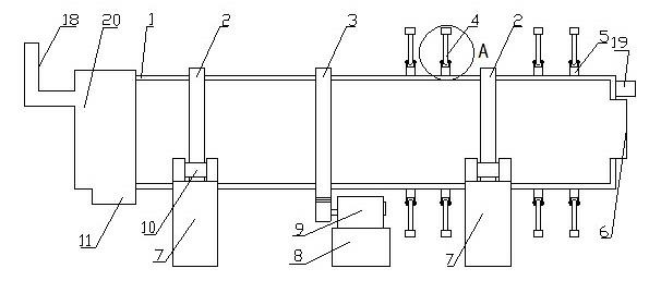
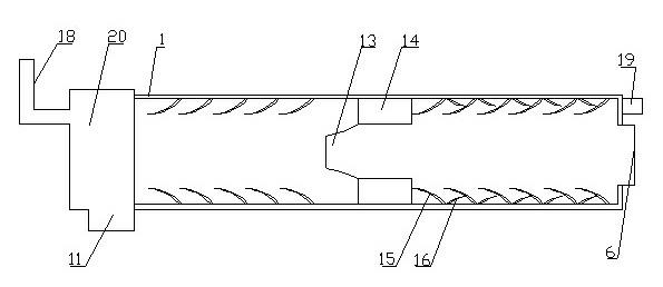
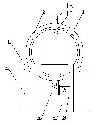
[0022] Embodiment 1: as figure 1 , 2 , 3, 4, and 5, a dryer vibration device includes a drum 1, a fixed sleeve 20 with an air inlet 18 and a discharge port 11 arranged on one side of the drum 1, and a fixed sleeve 20 arranged on the other side of the drum 1 The air outlet 19 and the feed port 6, the transmission gear 3 arranged on the outer wall of the drum 1, the reducer 9 connected with the transmission gear 3 through the gear, the motor 12 connected with the reducer 9 through the pulley, and the transmission gear 3 arranged on the The sliding wheel 2 on the outer wall of the drum 1 on both sides is matched with the roller shaft 10. It is characterized in that a vibrating hammer 4 is movably installed on the outer wall of the drum 1 through a support frame 5, and a filter bucket is arranged in the middle of the inner wall of the drum 1. 13. The inner wall of the drum 1 on both sides of the filter bucket 13 is provided with a forward flight board 15, and the reverse flight b...

Embodiment 2

[0024] Embodiment 2: as figure 1 , 2 , 3, 4, and 5, a dryer vibration device includes a drum 1, a fixed sleeve 20 with an air inlet 18 and a discharge port 11 arranged on one side of the drum 1, and a fixed sleeve 20 arranged on the other side of the drum 1 The air outlet 19 and the feed port 6, the transmission gear 3 arranged on the outer wall of the drum 1, the reducer 9 connected with the transmission gear 3 through the gear, the motor 12 connected with the reducer 9 through the pulley, and the transmission gear 3 arranged on the The sliding wheel 2 on the outer wall of the drum 1 on both sides is matched with the roller shaft 10. It is characterized in that a vibrating hammer 4 is movably installed on the outer wall of the drum 1 through a support frame 5, and a filter bucket is arranged in the middle of the inner wall of the drum 1. 13. The inner wall of the drum 1 on both sides of the filter bucket 13 is provided with a forward flight board 15, and the reverse flight b...

Embodiment 3

[0026] Embodiment 3: as figure 1 , 2 , 3, 4, and 5, a dryer vibration device includes a drum 1, a fixed sleeve 20 with an air inlet 18 and a discharge port 11 arranged on one side of the drum 1, and a fixed sleeve 20 arranged on the other side of the drum 1 The air outlet 19 and the feed port 6, the transmission gear 3 arranged on the outer wall of the drum 1, the reducer 9 connected with the transmission gear 3 through the gear, the motor 12 connected with the reducer 9 through the pulley, and the transmission gear 3 arranged on the The sliding wheel 2 on the outer wall of the drum 1 on both sides is matched with the roller shaft 10. It is characterized in that a vibrating hammer 4 is movably installed on the outer wall of the drum 1 through a support frame 5, and a filter bucket is arranged in the middle of the inner wall of the drum 1. 13. The inner wall of the drum 1 on both sides of the filter bucket 13 is provided with a forward flight board 15, and the reverse flight b...


PUM


Abstract

The invention relates to a drier vibrator, in particular relates to a drier vibrator which comprises a rotary drum, a fixed sleeve, an air outlet, a charge hole, a transmission gear, a reducer, a motor and sliding wheels, wherein the fixed sleeve is arranged at one side of the rotary drum and is provided with an air inlet and a discharge hole; the air outlet and the charge hole are arranged at the other side of the rotary drum; the transmission gear is arranged at the outer wall of the rotary drum; the reducer is connected with the transmission gear through a gear; the motor is connected with the reducer through a belt wheel; the sliding wheels are arranged the outer wall of the rotary drum at two sides of the transmission gear, and is matched with a rolling shaft; the outer wall of the rotary drum is provided with a vibration hammer through a bearing frame in a rotation mode; the middle part of the inner wall of the rotary drum is provided with a filtering funnel; the inner wall of the rotary drum at two sides of the filtering funnel is provided with forward shovelling plates; and the inner wall of the rotary drum between the filter funnel and the charge hole is provided with a reverse shovelling plate which is provided with a blanking hole. The drier vibrator provided by the invention has the advantages of resonable structure, good drying and crushing effect, and is convenient to use, manpower resouces are saved, and working efficiency is improved greatly.

Description

technical field [0001] The invention relates to a dryer, in particular to a dryer vibrating device capable of drying wet materials, transporting the dried wet materials to the outside along the barrel wall of the dryer, and preventing the wet materials from sticking to the barrel walls of the dryer. Background technique [0002] The dryer is a machine that uses heat to dry wet materials. According to the structure, there are tubular dryers, drum dryers, shaft dryers, boiling layer dryers and spiral dryers. Moisture evaporates and escapes to obtain solid materials with specified moisture content. The purpose of drying is to meet the needs of material use or further processing. [0003] The drum dryer is a contact type internal heating conduction drying machine. During the drying process, the heat is transferred from the inner wall of the drum to the outer wall, passing through the dried food materials attached to the outer wall of the drum, and evaporating the water on the ...

Claims


Application Information

Patent Timeline
Patent Type & Authority Applications(China)
IPC IPC(8): F26B25/04
Inventor 王国胜何晓慧
Owner YUZHOU WEILITE CHEM
Why Eureka
Try Eureka