
Clamp and method for testing pavement interlayer shear fatigue test piece

A pavement interlayer and testing method technology, applied in the direction of measuring devices, mechanical devices, instruments, etc., can solve the problems of interlayer shear fatigue without specific regulations, affecting the normal use performance and service life of the pavement, and damage to the base layer. The test method is simple and easy to implement, and the test equipment is simple and reliable.

Inactive Publication Date: 2011-06-15
CCCC FIRST HIGHWAY CONSULTANTS
View PDF3 Cites 25 Cited by
  • Summary
  • Abstract
  • Description
  • Claims
  • Application Information

AI Technical Summary

Problems solved by technology

Under the action of driving load, the interior of the pavement structure, especially the joint between layers, is prone to large shear stress and strain. Repeated shear stress and strain cause the interlayer bonding layer to break due to shear fatigue, and the pavement structure layer Delamination occurs, followed by cracks, pits, shifting and even damage to the base layer, which seriously affects the normal performance and service life of the pavement
[0003] At present, no one has studied the interlayer shear fatigue of pavement structures at home and abroad, and no one has been involved in the shear fatigue test between layers of structures. At present, the road structure design is seriously inconsistent with the actual use, that is, the pavement structure has not been in a completely continuous state during the actual use process, so how to effectively characterize the interlayer shear fatigue characteristics of the pavement structure is a problem that needs to be solved to ensure the normal use of the pavement

Method used


Image

  • Clamp and method for testing pavement interlayer shear fatigue test piece
  • Clamp and method for testing pavement interlayer shear fatigue test piece
  • Clamp and method for testing pavement interlayer shear fatigue test piece

Examples


Embodiment

[0041] 1. The large Marshall specimen of asphalt mixture with a diameter of 150mm was prepared by rotary compaction method, and the cement-stabilized macadam specimen with a diameter of 150mm was prepared by compaction method, and the penetrating layer oil and sealing material were applied on the surface of cement-stabilized macadam , and then place the asphalt mixture large Marshall specimen on the cement-stabilized macadam specimen coated with permeable oil, and use a press for static pressure molding, and let the specimen stand for more than 12 hours before proceeding to the next step Experimental operation. The number of samples in the same group shall not be less than 3.

[0042] 2. Place the test piece and the fixture for shear fatigue in a 15°C environment box, and keep the holding time for no less than 6 hours.

[0043] 3. Put the specimen into the shear fatigue fixture. It should be ensured that the sheared surface of the test piece and the combined surface of the ...


PUM


Abstract

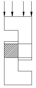
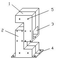
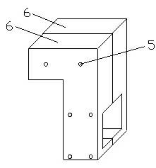
The invention relates to a clamp and a method for testing a pavement interlayer shear fatigue test piece. At present, no one does research on interlayer shear fatigue of a pavement structure at home and abroad. The invention provides the clamp for testing the pavement interlayer shear fatigue test piece, which comprises an upper clamp component and a lower clamp component; the upper clamp component and the lower clamp component are abnormally-shaped blocks of which the longitudinal sections are L-shaped; each abnormally-shaped block is formed by splicing two same parts; the upper clamp component and the lower clamp component are buckled; and through slots are formed on the middle parts of transverse buckling parts. By using the structure, left and right ends of the test piece are fixed by the upper clamp and the lower clamp; a bonding layer in the middle of the test piece is positioned at the combined part of the through slots of the two clamps; and a vertical waveform load parallel to the bonding layer in the middle of the test piece is exerted to obtain a relation between a shear stress (strain) and an experimental loading frequency, so a fatigue shear characteristic parameter of the test piece can be obtained.

Description

technical field [0001] The invention belongs to the technical field of pavement engineering equipment, and relates to a shear fatigue test device for pavement structural layers under repeated loads, in particular to a fixture for testing pavement interlayer shear fatigue specimens and a testing method thereof. Background technique [0002] The pavement structure is a multi-layer composite system composed of different materials. Due to the difference in materials, the deformation between different structural layers cannot be consistent and coordinated. Therefore, it is generally required to spread sticky oil and permeable layers between the structural layers. It is hoped that the deformation coordination of different structural layers can be achieved through this interlayer bonding measure. Under the action of driving load, the interior of the pavement structure, especially the joint between layers, is prone to large shear stress and strain. Repeated shear stress and strain c...

Claims


Application Information

Patent Timeline
IPC IPC(8): G01N19/02
Inventor 陈团结李刚王争军白雪梅王鹏翔李智曹海波
Owner CCCC FIRST HIGHWAY CONSULTANTS
Learn More