Supercharge Your Innovation With Domain-Expert AI Agents!

Multi-stage oriented logging wave detector device

A geophone and logging technology, which is used in seismology, wellbore/well components, seismic signal receivers, etc. The data cannot fully reflect the geological structure, and the direction of the shear wave component geophone cannot be controlled, so as to achieve the effect of good inter-stage shock absorption and isolation function, simple structure, and accurate pushing position.

Inactive Publication Date: 2012-10-17
中国石化集团胜利石油管理局地球物理勘探开发公司 +1
View PDF5 Cites 0 Cited by
  • Summary
  • Abstract
  • Description
  • Claims
  • Application Information

AI Technical Summary

Problems solved by technology

With the in-depth research and practice of micro-logging vertical seismic section, this seismic observation method, this type of device still has the following limitations: (1) The main body of the single-stage logging detector determines that it can only be used during use. The main body is collected point by point according to a certain rule, and repeatedly pushes against, repeatedly excites the source, and repeatedly receives signals. The seismic signals received by multiple single-point excitations and single-point receptions cannot well reflect the objective situation of the region's geology; (2) Due to the soft lifting rope structure, the direction of the shear wave component geophone cannot be controlled in the well, and the shear wave component cannot always be ensured. Maintain a specific angle relationship with the source direction
Therefore, the final processed seismic data will not fully reflect the actual geological structure, and cannot accurately analyze the propagation and attenuation laws of the near-source wave field.

Method used


Image

  • Multi-stage oriented logging wave detector device
  • Multi-stage oriented logging wave detector device
  • Multi-stage oriented logging wave detector device

Examples


Embodiment Construction

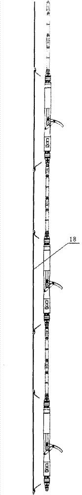
[0018] From figure 1 , figure 2 It can be seen from the figure that a multi-stage directional geophone device of the present invention is provided with several geophone units, and each geophone unit includes a cylindrical main body and a Three-component geophone and well wall pushing device, etc.

[0019] The tubular main body of the present invention is a slender cylindrical structure, and its main structural composition includes a geophone fixed body 3, a support arm pushing against a connecting body 4, and an electric push rod connecting body 5. The parts are connected by threads, and the threaded connections are provided with With jacking screws. Therefore, it is ensured that the pin shaft hole of the signal receiving part is parallel and consistent with the pin shaft hole of the power driving part.

[0020] The shaft wall pushing device in the present invention is composed of an electric push rod 7, a support arm 6, and a connecting rod mechanism 8. Towards the contr...


PUM


Abstract

The invention relates to a multi-stage oriented logging wave detector device which is provided with a plurality of logging wave detector units, wherein each logging wave detector unit comprises a cylindrical main body, a tricomponent wave detector arranged on the cylindrical main body and a well wall pushing device; two ends of the logging wave detector units are connected with fixed shock absorption and insulation units, and interstage hard connecting rod assemblies are arranged between the shock absorption and insulation units; and the plurality of logging wave detector units, the shock absorption and insulation units and the interstage hard connecting rod assemblies are connected in series to form the multi-stage oriented logging wave detector device to realize the simultaneous receiving of multiple position points of the wave detector in a well. In a construction process, the number of stages can be increased and reduced according to a specific construction requirement. The devicehas the advantages of simple and reasonable structure, convenience of connection and disassembly, flexibility of stage control, accuracy of pushing position and capabilities of oriented construction and receiving as well as good interstage shock absorption and insulation function and is suitable for logging wave detection of petroleum seismic exploration, mining geology, constructional engineering, and the like.

Description

Technical field [0001] The invention relates to a geophone device for oil exploration, in particular to a multi-level directional logging geophone device suitable for small well diameters and capable of directional construction and reception. Background technique [0002] A lot of research and practice have shown that the low-speed zone on the surface absorbs high frequencies very seriously, so if the geophone can be placed below the low-speed zone to receive, it will reduce a lot of high-frequency absorption. Some foreign high-resolution construction teams use disposable downhole geophones. If the geophone is buried in a blast well with a depth of 15m for reception, one geophone is placed in each well. In the rolling forward construction process, the shot point is the past receiver point, and the receiver is no longer recovered. The improvement in profile quality obtained by this method is evident. [0003] In response to this situation, large-scale well logging equipmen...

Claims


Application Information

Patent Timeline
Patent Type & Authority Patents(China)
IPC IPC(8): G01V1/18G01V1/52E21B49/00
Inventor 于富文颜永安胡立新申恒广刘志田孙中心杨德宽赵冰吴学兵戚全宋智勇李艳艳王文争
Owner 中国石化集团胜利石油管理局地球物理勘探开发公司
Features
  • R&D
  • Intellectual Property
  • Life Sciences
  • Materials
  • Tech Scout
  • Unparalleled Data Quality
  • Higher Quality Content
  • 60% Fewer Hallucinations
Learn More