Supercharge Your Innovation With Domain-Expert AI Agents!

Fuse detection circuit

A technology for detecting circuits and fuses, applied in circuits, electrical components, emergency protection devices, etc., can solve the problems of complex indicator structure and high cost, and achieve the effect of low cost and simple circuit

Inactive Publication Date: 2011-06-15
易事特电力系统技术有限公司
View PDF5 Cites 4 Cited by
  • Summary
  • Abstract
  • Description
  • Claims
  • Application Information

AI Technical Summary

Problems solved by technology

The signal transmitting device is a remote device that can transmit a signal to the state of the fuse. This kind of fuse state indicator has a complex structure and high cost.

Method used


Image

  • Fuse detection circuit
  • Fuse detection circuit

Examples


Embodiment 1

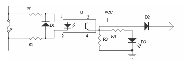
[0024] This embodiment provides a fuse detection circuit, including a fuse F, a photocoupler U, a fault location circuit, and a fault alarm circuit;

[0025] Pin 1 of photocoupler U is connected to one end of fuse F;

[0026] Connect pin 2 of photocoupler U to the other end of fuse F;

[0027] Pin 3 of the optocoupler U is connected to DC;

[0028] Pin 4 of the optocoupler U is connected to the input end of the fault location circuit and the output end of the fault signal; in this embodiment, when the fuse F is open, a pressure difference is formed at both ends of the fuse F to drive the optocoupler U, and the optocoupler U outputs The isolated signal is transmitted to the fault signal alarm system and the fault location circuit, and the position of the fault fuse F is quickly located by using the lighting of the light-emitting diode in the fault location circuit. The present invention uses a simple circuit to realize fault alarm, protection and positioning, and the cost is l...

Embodiment 2

[0039] On the basis of Embodiment 1, this embodiment also includes a diode D1, the cathode of D1 is connected to pin 1 of the optocoupler U;

[0040] The positive pole of D1 is connected with pin 2 of optocoupler U.

[0041] The purpose of adding D1 in this embodiment is to protect the photocoupler and prevent the photocoupler U from being damaged due to excessive back pressure.

[0042] A fuse detection circuit of the present invention can be used in multiple connections, and the fault signal output terminals of multiple fuse detection circuits are connected to the fault detection circuit to realize the purpose of simultaneous detection of multiple fuse faults.


PUM


Abstract

The invention relates to the technical field of power supply circuits, in particular to a fuse detection circuit. The fuse detection circuit comprises a fuse F, a photoelectric coupler U, a fault positioning circuit and a fault alarm circuit; the 1st pin of a light emitting diode (LED) of the photoelectric coupler U is connected with one end of the fuse F; the 2nd pin of the LED of the photoelectric coupler U is connected with the other end of the fuse F; the 3rd pin of the photoelectric coupler U is connected with a direct current; and the 4th pin of the photoelectric coupler U is connected with the input end of the fault positioning circuit and a fault signal output end. When the fuse F is open-circuited, two ends of the fuse F form voltage difference to drive the photoelectric coupler U, the photoelectric coupler U outputs isolation signals to a fault signal alarm system and the fault positioning circuit, and the LED in the fault positioning circuit is lightened to quickly position the position of the fault fuse F; and by using the simple circuit, fault alarm, protection and positioning are realized, and the cost is low.

Description

technical field [0001] The invention relates to the technical field of power supply circuits, in particular to a fuse detection circuit. Background technique [0002] As an essential electronic component for circuit protection and circuit fault location, fuses are widely used in various fields of electronic circuits. [0003] Chinese invention patent (application number: 200880113468.4) discloses a fuse status indicator that can be equipped with a disconnecting device with a fuse. The fuse state indicator includes a housing containing an electrical circuit, sensing means for sensing the disconnected state of the electrical circuit, and a circuit connection of a fuse configured to be electrically connected to the disconnecting means to complete the connection of the sensing means to the disconnecting means conductors, and signal transmitters. The detecting device is configured to transmit a signal to the signal transmitting device for determining the working state of the fu...

Claims


Application Information

Patent Timeline
IPC IPC(8): H01H85/30
Inventor 戴宝锋
Owner 易事特电力系统技术有限公司
Features
  • R&D
  • Intellectual Property
  • Life Sciences
  • Materials
  • Tech Scout
  • Unparalleled Data Quality
  • Higher Quality Content
  • 60% Fewer Hallucinations
Learn More