
LED control method and equipment

A technology for control equipment and control methods, which is applied in energy-saving control technology, lighting devices, light sources, etc., and can solve problems such as impedance mismatch of communication lines, limiting transmission distance, and limiting LED installation distance.

Active Publication Date: 2011-06-15
重庆星河光电科技股份有限公司
View PDF6 Cites 9 Cited by
  • Summary
  • Abstract
  • Description
  • Claims
  • Application Information

AI Technical Summary

Problems solved by technology

[0005] In view of this, the present invention provides an LED control method and device to solve the problem that in the existing equipment, when the number of sub-controllers increases to a certain number, the sub-controllers are respectively connected to the main controller, which will cause problems on the entire communication line. Impedance does not match, resulting in the failure of communication, limiting the transmission distance, and thus limiting the installation distance of LEDs

Method used


Image

  • LED control method and equipment
  • LED control method and equipment
  • LED control method and equipment

Examples


Embodiment Construction

[0033] The following will clearly and completely describe the technical solutions in the embodiments of the present invention with reference to the accompanying drawings in the embodiments of the present invention. Obviously, the described embodiments are only some, not all, embodiments of the present invention. Based on the embodiments of the present invention, all other embodiments obtained by persons of ordinary skill in the art without making creative efforts belong to the protection scope of the present invention.

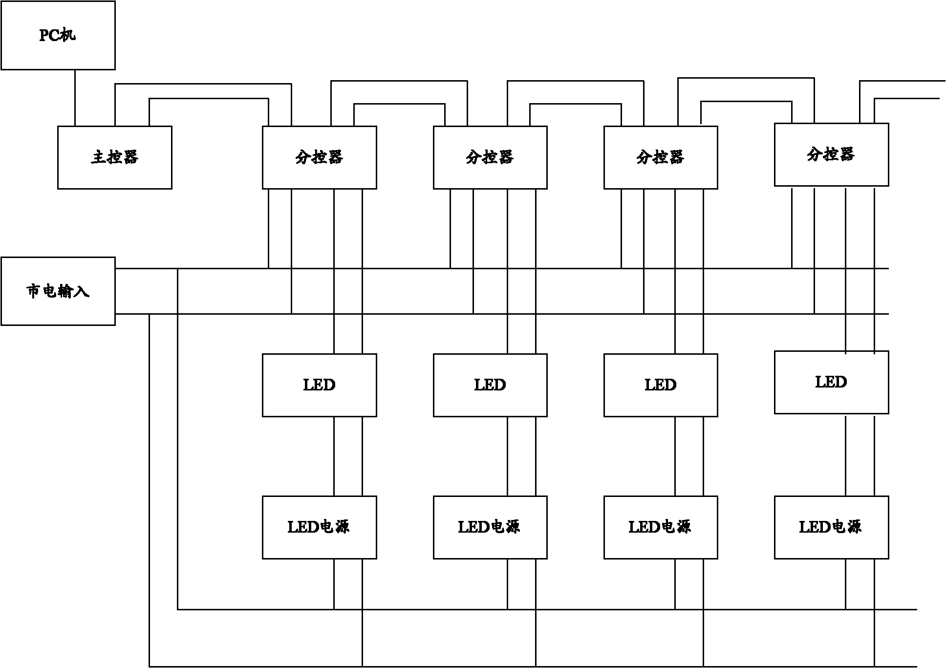
[0034] The applicant found through research that the main controller and the sub-controllers in the current LED control equipment are connected in parallel. As we all know, when a circuit is connected in parallel, every time a device is added to the output, the impedance of the newly added device will cause the impedance of the output to change. impedance. Similarly, for LED control equipment, every additional sub-controller will cause the impedance of the fr...


PUM


Abstract

The invention discloses an LED control method and equipment. The LED control equipment comprises a PC (Personal Computer), a master controller and a plurality of branch controllers; the plurality of branch controllers are connected in series with the master controller; the PC is connected with the master controller; and the branch controllers are used for controlling LEDs. By applying the technical scheme, the plurality of branch controllers are connected in series with the master controller, when a branch controller is additionally provided, the branch controller is needed to match with an impedor of a device arranged at the front end of the branch controller, but not needed to match with impedors of all devices, therefore, the connection number of the branch controllers is increased, and the mounting distance of the LEDs is further increased.

Description

technical field [0001] The invention relates to the technical field of LED equipment, in particular to an LED control method and equipment. Background technique [0002] At present, the communication method based on RS485 has been widely used in various industrial control systems because of its cheap and easy networking and a series of advantages. For example: LED control equipment. [0003] The LED control equipment uses RS485 as the main controller. After the main controller recognizes the signal obtained from the host, it transmits it to the sub-controllers in the device that are respectively connected to the main controller, and then the sub-controllers control according to the received signals. LED. [0004] Theoretically speaking, multiple sub-controllers can be connected to one RS485 interface bus, for example: RS485 with a special chip can already connect 256 sub-controllers. However, this is not the case in actual use. Since the sub-controllers are respectively ...

Claims


Application Information

Patent Timeline
Patent Type & Authority Applications(China)
IPC IPC(8): H05B37/02H04L12/40
CPCY02B20/42Y02B20/40
Inventor 余水廖隆盛黄敏
Owner 重庆星河光电科技股份有限公司
Learn More