Capacitance type vibration sensor

一种振动传感器、静电电容的技术,应用在传感器、静电换能器传声器、半导体静电换能器等方向,能够解决难以制作低干扰振动传感器、振动传感器低频特性变差、振动传感器S/N比变差等问题,达到声音阻抗降低、良好低频特性、减小低频特性的降低的效果

Active Publication Date: 2011-06-15
MMI SEMICON CO LTD
View PDF2 Cites 10 Cited by
  • Summary
  • Abstract
  • Description
  • Claims
  • Application Information

AI Technical Summary

Problems solved by technology

[0034] However, in order to reduce the interference caused by the thermal noise of the ventilation hole, when the gap of the ventilation hole is widened, or the length of the ventilation hole in the direction of ventilation is shortened, the low-frequency characteristics of the vibration sensor will be deteriorated
On the contrary, in order to prevent the reduction of low-frequency characteristics, when the length t of the ventilation direction of the ventilation hole is lengthened or the cross-sectional area Sv of the ventilation hole is reduced, the interference caused by the thermal noise of the ventilation hole increases, and the S / N ratio of the vibration sensor deteriorates
[0035] For this reason, in the structure of the existing vibration sensor, low noise and good low-frequency characteristics of the vibration sensor are in the relationship of comprehensive adjustment (tray-doof), and it is difficult to manufacture a vibration sensor with low noise and good low-frequency characteristics.

Method used


Image

  • Capacitance type vibration sensor
  • Capacitance type vibration sensor
  • Capacitance type vibration sensor

Examples


no. 1 approach

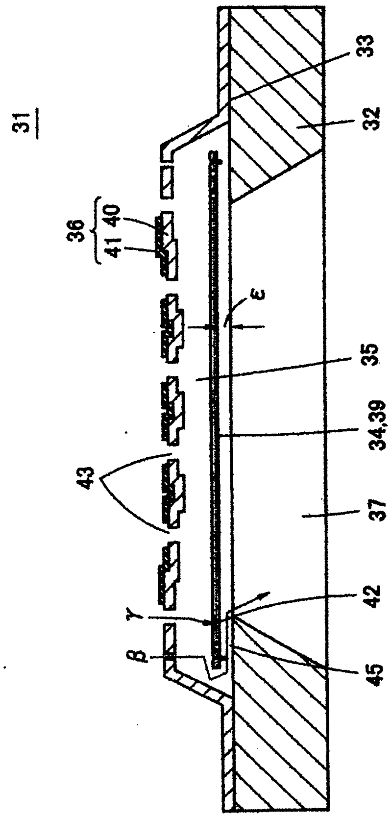
[0073] Below, refer to Figure 3 ~ Figure 7 The first embodiment of the present invention will be described. image 3 It is a schematic cross-sectional view showing the capacitance type vibration sensor 31 of the first embodiment. Figure 4 It is an exploded perspective view of the vibration sensor 31. In addition, Figure 5 It is a plan view of the vibration sensor 31. Image 6 It is a plan view of a state where the fixed electrode plate on the upper surface of the vibration sensor 31 is removed. Figure 7 It is a figure for demonstrating the effect of this embodiment, and shows a part of the cross section of the vibration sensor 31.

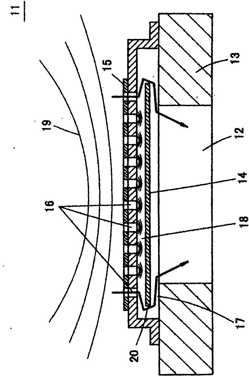
[0074] The vibration sensor 31 is an electrostatic capacitance type sensor. A vibration electrode plate 34 is provided on the upper surface of a silicon substrate 32 via an insulating coating 33, and a fixed electrode plate 36 is provided thereon via a small air gap 35. The vibration sensor 31 is mainly used as a sound sensor and a condenser micro...

no. 2 approach

[0093] Picture 9 (a) is an enlarged cross-sectional view showing a part of the vibration sensor of the second embodiment, Picture 9 (b) is a plan view showing a part of the silicon substrate 32 located around the cavity 37. In this embodiment, the exhaust portions 51 and 52 are provided on the base plate 42 at positions where the ventilation holes 45 are provided. The exhaust portion 51 is a through hole that penetrates the silicon substrate 32 up and down, and the exhaust portion 51 is a bottomed recess (that is, a hole blocked on one side).

[0094] In the case of the through-hole-shaped exhaust portion 51, like the exhaust portion 42 of the first embodiment, it is possible to reduce the interference due to thermal noise without reducing the acoustic impedance of the vent hole 45.

[0095] In the case of the concave exhaust portion 52, the distance between the bottom surface of the concave portion and the lower surface of the vibrating electrode plate 34 becomes longer by provi...

no. 3 approach

[0098] Picture 10 Is an enlarged cross-sectional view showing a part of the vibration sensor of the third embodiment, Picture 11 It is a plan view of the silicon substrate 32 used in this vibration sensor. In this embodiment, in the ventilation hole 45, a groove-shaped exhaust portion 61 is provided on the upper surface of the silicon substrate 32 so as to surround the cavity 37. In the illustrated example, two exhaust portions 61 are provided, but there may be one, and as long as the acoustic impedance is not too low, there may be three or more. In addition, the groove of the exhaust part 61 does not need to be annular, and linear grooves may be formed along each side.

[0099] In such an embodiment, as in the case of the first and second embodiments, the interference caused by the thermal noise in the vent hole 45 can be reduced, and the good low-frequency characteristics can be made difficult to reduce.

[0100] In addition, in the vent hole 45, a groove-shaped exhaust portio...


PUM


Abstract

The invention provides a capacitance type vibration sensor. On the top surface of a silicon substrate (32) having a hollow portion (37), a vibration electrode plate (34) which performs film vibration when receiving vibration is provided. Moreover, over the vibration electrode plate (34), a fixed electrode plate (36) through which a plurality of acoustic perforations (43) are opened in the thickness direction, arranging the vibration electrode plate (34) and the fixed electrode plate (36) opposite to each other. Surrounding the hollow part (37), between the upper surface of a silicon substrate (32) and the lower surface of the vibration electrode plate (34), a vent hole (45) is provided to allow an air gap (35) between the vibration electrode plate (34) and the fixed electrode plate (36) to communicate with the hollow part (37). In an area corresponding to the vent hole (45), an air escape portion (42) in the state of a plurality of through holes is opened in the vibration electrode plate (34).

Description

Technical field [0001] The present invention relates to an electrostatic capacitance type vibration sensor, in particular to a vibration sensor with a small size manufactured using MEMS (Micro Electro Mechanical System) technology or micro processing technology. Background technique [0002] (Basic structure of vibration sensor) [0003] figure 1 Shows the basic structure of a capacitive vibration sensor. In the vibration sensor 11, a vibration electrode plate 14 is arranged on the upper surface of a substrate 13 having a cavity 12 in the center, and the upper part of the vibration electrode plate 14 is covered by a fixed electrode plate 15. A plurality of sound holes 16 (acoustic holes) penetrate through the fixed electrode plate 15 up and down. In addition, around the cavity 12, a ventilation hole 17 is provided between the upper surface of the substrate 13 and the lower surface of the vibrating electrode plate 14. The ventilation hole 17 is used to make the space between the v...

Claims


Application Information

Patent Timeline
Patent Type & Authority Applications(China)
IPC IPC(8): H04R19/04
CPCH04R19/005H04R19/04H04R31/006
Inventor 笠井隆鹤龟宜崇
Owner MMI SEMICON CO LTD
Why Eureka
Try Eureka