Flexible joint leakage oil collecting device for plane fuel duct

A collection device and flexible joint technology, applied in the direction of pipe/pipe joint/pipe fitting, pipe element, adjustable connection, etc., can solve the problem of inconsistent bending deformation between oil leakage collection device and flexible joint, axial limit deformation of aircraft fuel conduit, flexibility Joint loss of bending ability and other problems, to solve the problem of oil leakage of flexible joints, ensure the safety of aircraft use and flight, and work reliably

Active Publication Date: 2011-06-22
XIAN AIRCRAFT DESIGN INST OF AVIATION IND OF CHINA
View PDF3 Cites 7 Cited by
  • Summary
  • Abstract
  • Description
  • Claims
  • Application Information

AI Technical Summary

Problems solved by technology

The technical structure of the oil leakage collection device described in Patent No. 201020120886.0 does not limit the minimum clearance of the oil leakage collection device, and the axial limit deformation or installation error of the aircraft fuel pipe makes the gap of the oil leakage collection device smaller than that of the flexible joint connection. If the gap between the fuel pipes of the two aircrafts is serious, the oil leakage collection device will be damaged or the flexible joint will lose its bending ability, and no control measures are taken for the bending deformation of the oil leakage collection device. The bending deformation of the oil leakage collection device and the flexible joint is inconsistent, and if the situation is serious, it will also cause damage to the oil leakage collection device or the loss of bending ability of the flexible joint

Method used


Image

  • Flexible joint leakage oil collecting device for plane fuel duct
  • Flexible joint leakage oil collecting device for plane fuel duct

Examples


Embodiment Construction

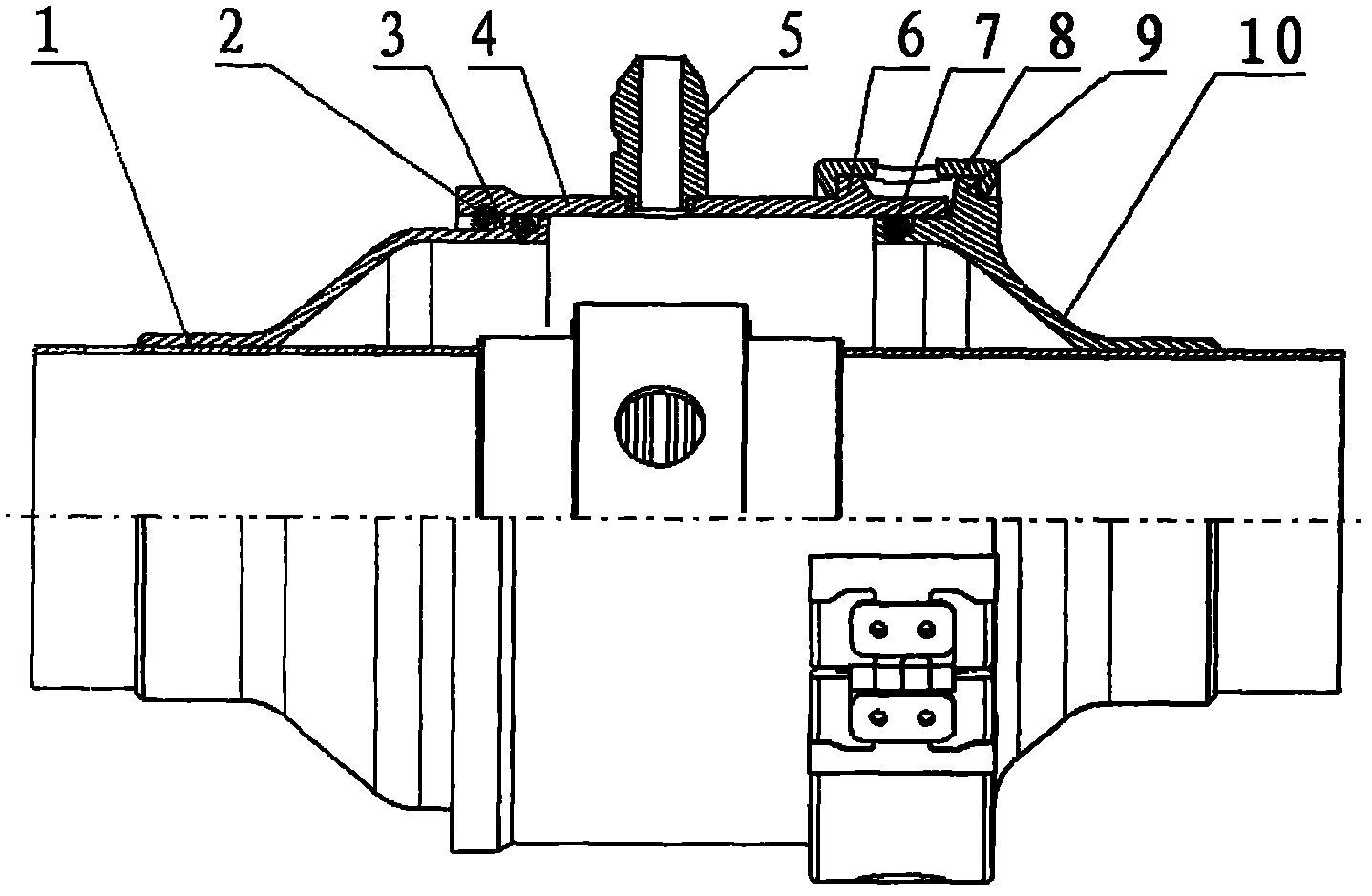
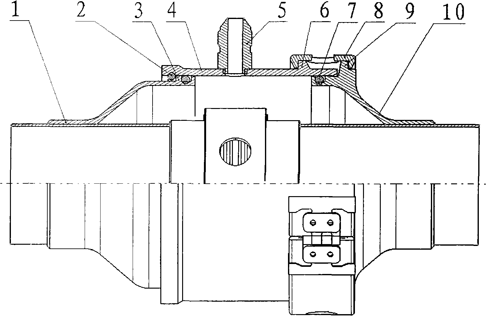
[0011] The present invention comprises a left supporting sleeve 1, a spring retaining ring 2, a block 3, a connecting sleeve 4, an oil leakage nozzle 5, a left flange 6, a sealing ring 7, a hoop 8, a right flange 9, and a right supporting sleeve 10. One end of the left support sleeve 1 and one end of the right support sleeve 10 are respectively welded on the aircraft fuel conduits at the left and right ends of the flexible joint. The other end of the support sleeve 10 is provided with a sealing groove, and the outer side of the sealing groove is provided with a right flange 9 for installing a clip; one end of the connecting sleeve 4 is provided with a card slot for installing a spring retaining ring 2, and the other end is provided for installing a clip The left flange 1 of the hoop 8, the connecting sleeve 4 are installed on the left supporting sleeve 1 and the right supporting sleeve 10 through the clamping hoop 8 and the spring retaining ring 2, the oil leakage nozzle 5 is w...


PUM


Abstract

The invention belongs to the technology of plane pipeline systems and relates to a duct flexible joint leakage oil collecting device used for flexibly connecting plane fuel ducts. The collecting device comprises a left supporting sleeve, a spring collar, a connecting sleeve, a sealing ring, a leakage oil pipe nozzle, a collar clamp and a right supporting sleeve, wherein one ends of the left supporting sleeve and the right supporting sleeve are respectively welded on the plane fuel ducts at the left end and the right end of a flexible joint; the other end of the left supporting sleeve is provided with a barricade; the barricade is provided with a sealing groove; the other end of the right supporting sleeve is provided with the sealing groove; a right flange used for installing the collar clamp is arranged at the outer side of the sealing groove; one end of the connecting sleeve is provided with a slot for installing the spring collar, and the other end of the connecting sleeve is provided with a left flange used for installing the collar clamp; the connecting sleeve is installed on the left supporting sleeve and the right supporting sleeve through the collar clamp and the spring collar; and the leakage oil pipe nozzle is welded on the connecting sleeve. The collecting device has a flexible compensation function and guarantees the work reliability.

Description

technical field [0001] The invention belongs to the aircraft pipeline system technology, and relates to an oil leakage collecting device for protecting the oil leakage of the flexible joint of the aircraft fuel conduit. Background technique [0002] The oil leakage failure of the flexible joint of the aircraft fuel conduit often occurs, and the oil leakage of the fuel system directly affects the use of the aircraft and flight safety. The oil is collected, and the leaked oil can be discharged out of the machine through the oil leakage nozzle and the oil leakage conduit at the same time, and by checking whether there is oil at the outlet, it can be judged whether the flexible joint is leaking oil. The technical structure of the oil leakage collection device described in Patent No. 201020120886.0 does not limit the minimum clearance of the oil leakage collection device, and the axial limit deformation or installation error of the aircraft fuel pipe makes the gap of the oil leak...

Claims


Application Information

Patent Timeline
Patent Type & Authority Applications(China)
IPC IPC(8): F16L27/10F16L55/00
Inventor 林厚焰王晓阳赵平安李小刚
Owner XIAN AIRCRAFT DESIGN INST OF AVIATION IND OF CHINA
Why Eureka
Try Eureka