Electric motor, particularly outer rotor motor

A technology of electric motors and external rotors, applied in the field of electric motors, can solve problems such as interference, and achieve the effect of small noise formation and good cooling

Active Publication Date: 2011-06-22
施乐百股份公司
View PDF3 Cites 15 Cited by
  • Summary
  • Abstract
  • Description
  • Claims
  • Application Information

AI Technical Summary

Problems solved by technology

In addition, due to the pronounced noise formation at the mutually facing edges of the stator-side and rotor-side cooling fins, which is disturbing in motor applications

Method used


Image

  • Electric motor, particularly outer rotor motor
  • Electric motor, particularly outer rotor motor
  • Electric motor, particularly outer rotor motor

Examples


Embodiment Construction

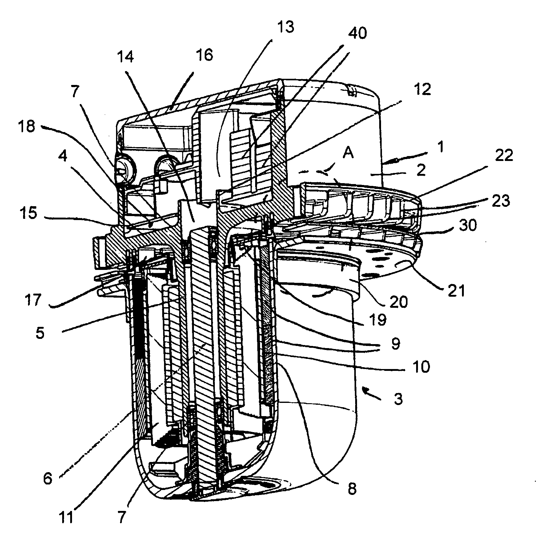
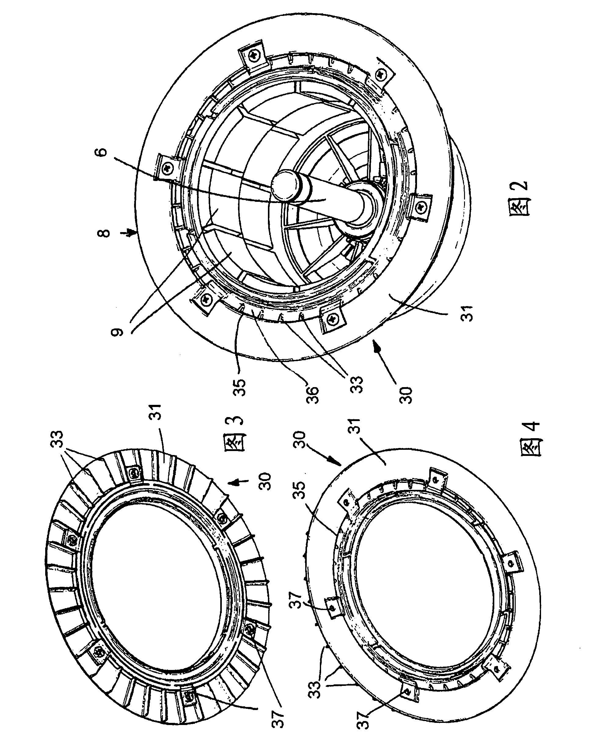
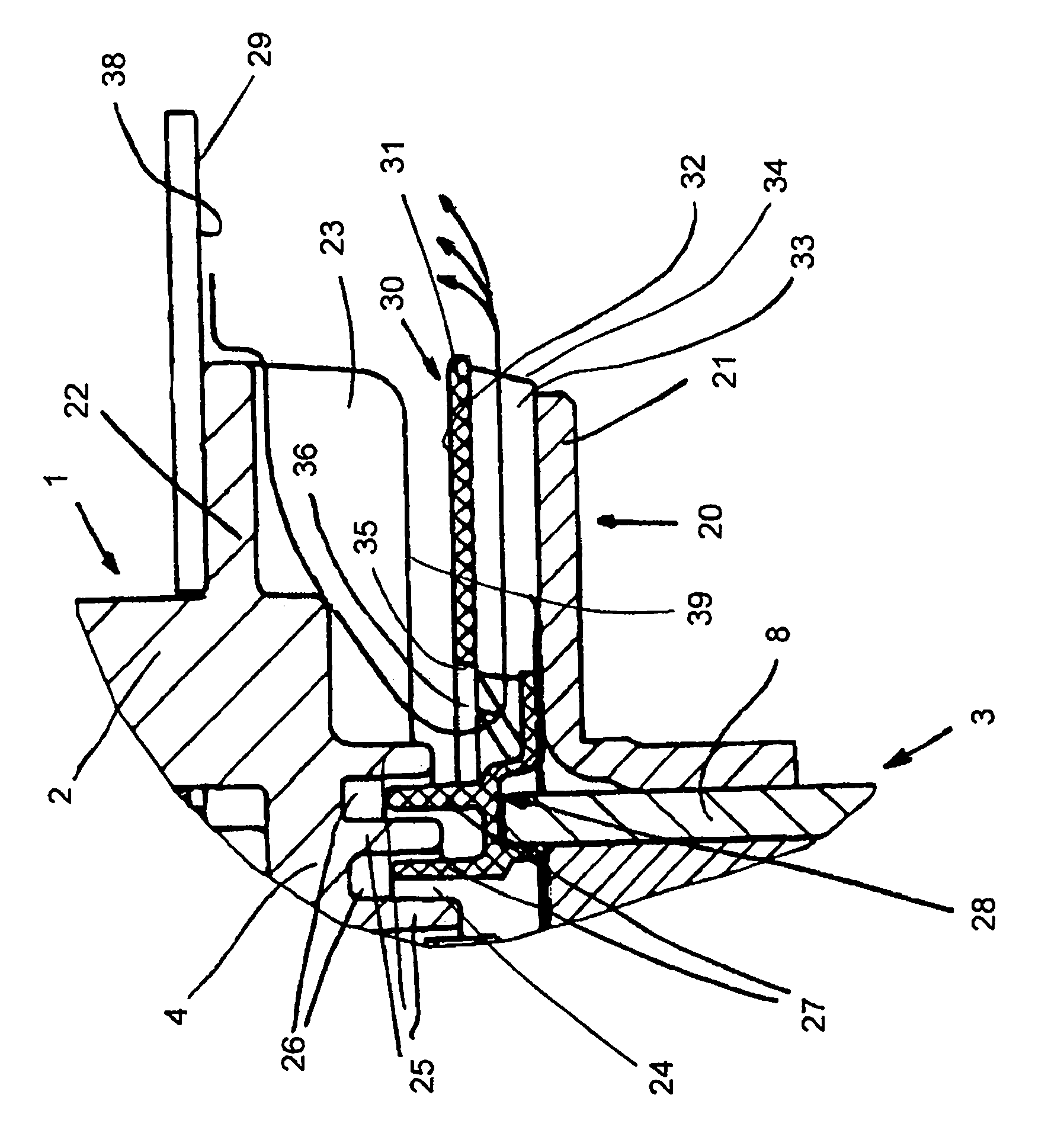
[0025] In the exemplary embodiment, the electric motor is an external rotor motor, which can be, for example, an electronically commutated DC motor. The electric motor has a stator sleeve 1 with a housing 2, which is preferably designed cylindrically. At its end facing the rotor 3 , the stator sleeve 1 has a base 4 , from the center of which protrudes a sleeve-shaped bushing 5 , which protrudes into the rotor 3 . The bushing 5 is advantageously formed in one piece with the base 4 . The rotor shaft 6 is rotatably supported in the bushing 5 with two bearings 7 near the upper end and the lower end. The bearing 7 is in the embodiment a ball bearing, but can be any other suitable bearing.

[0026] The rotor 3 has a rotor housing 8 , on the inside of which permanent magnets 9 are fastened. The permanent magnets surround a rotor lamination 11 (Rotor lamination), which is provided with rotor coils in a known manner, while forming an annular air gap 10 .

[0027] The bushing 5 exte...


PUM


Abstract

An electric motor has a stator bushing (1) in which components that generate heat are disposed; a rotor housing (8) which has a conveying element disposed therein. The air conveying element has a top side (32) that is facing the stator bushing and that is at least basically smooth. In-taken air flow can be turned and guided reliably by the top side (32). The uniform air flow through the top side (32) can cause optimal cooling. In addition, because the top side (32) is basically smooth, the motor operation causes only lowest noise even in high rotation speed.

Description

technical field [0001] The invention relates to an electric motor according to the preamble of claim 1 , in particular an external rotor motor. Background technique [0002] Electric motors are known in which the stator sleeve has cooling elements in the form of cooling fins on the outside close to the rotor housing, which are arranged at a distance from one another and distributed uniformly along the circumference of the stator sleeve. These fins lie opposite the rotor-side fins forming the air conveying element. Due to the cooling fins rotating relative to each other during operation of the electric motor, external air is sucked in as cooling air and introduced between the cooling fins rotating relative to each other. Good air guidance along the cooling fins is thus not possible. Furthermore, since the edges of the stator-side and rotor-side cooling fins facing one another noticeably generate noise, which is disturbing when used in electric motors. [0003] Electric mot...

Claims


Application Information

Patent Timeline
Patent Type & Authority Applications(China)
IPC IPC(8): H02K29/00H02K5/18H02K9/04
CPCH02K9/06H02K1/2786H02K1/32H02K5/18H02K1/2791H02K21/22H02K5/207H02K2205/09
Inventor J·克诺尔T·施图尔姆
Owner 施乐百股份公司
Why Eureka
Try Eureka