Ethernet ring network link failure recovery method, Ethernet ring network and node equipment

A technology for fault recovery and equipment, applied in the field of communications, can solve the problem of long convergence time for fault recovery, and achieve the effects of avoiding multi-link failures, improving link recovery convergence time, and satisfying the convergence time.

Active Publication Date: 2013-06-19
RUIJIE NETWORKS CO LTD
View PDF3 Cites 0 Cited by
  • Summary
  • Abstract
  • Description
  • Claims
  • Application Information

AI Technical Summary

Problems solved by technology

[0015] The embodiment of the present invention provides a link failure recovery method of the Ethernet ring network, the Ethernet ring network and the node equipment, which are used to solve the problem that when the direct link of two non-master node equipment fails, some link communication terminals will appear. Failure Recovery Convergence Time Too Long

Method used


Image

  • Ethernet ring network link failure recovery method, Ethernet ring network and node equipment
  • Ethernet ring network link failure recovery method, Ethernet ring network and node equipment
  • Ethernet ring network link failure recovery method, Ethernet ring network and node equipment

Examples


Embodiment 1

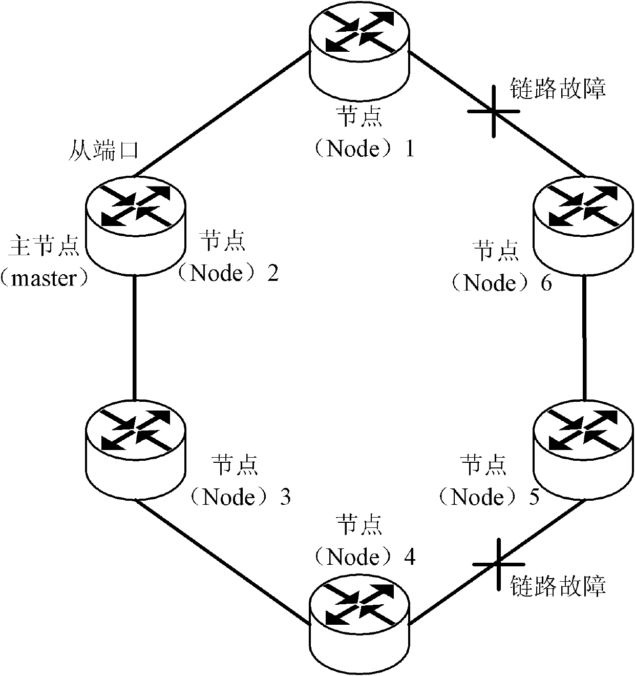
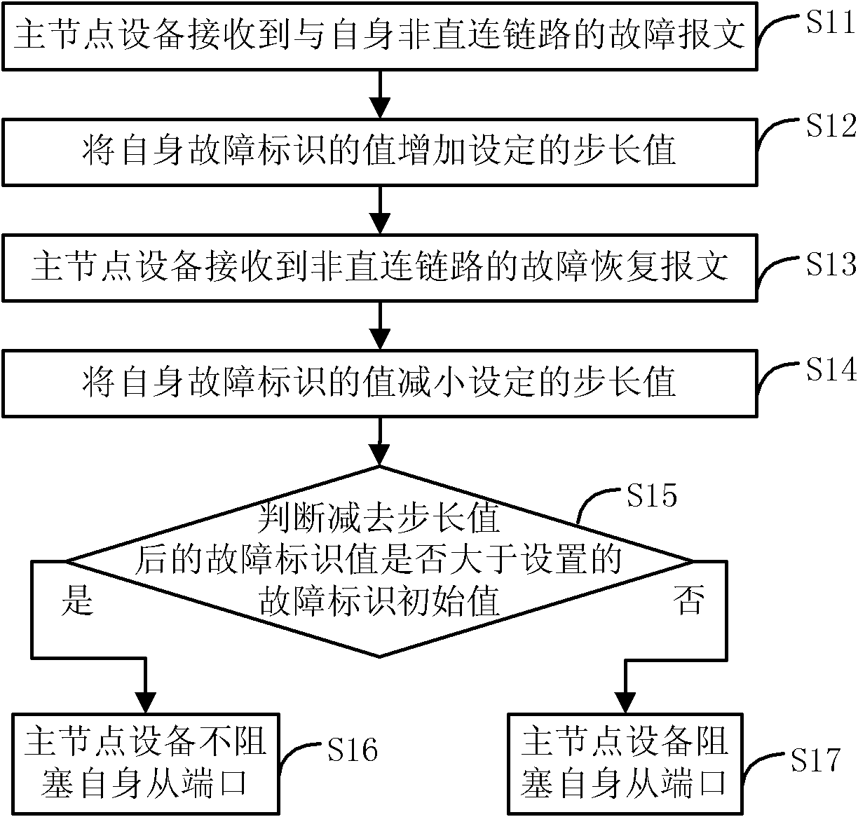
[0054] The Ethernet ring network link failure recovery method provided by Embodiment 1 of the present invention has a process as follows figure 2 As shown, the execution steps are as follows:

[0055] Step S11: The master node device receives a failure message of a link not directly connected to itself.

[0056] The transit node device detects its own link failure, and sends a failure message (link down) to the master node device to notify the master node device of its own link failure. When the master node device receives the fault message, it will judge whether it is a fault message directly connected to itself.

[0057] When the master node device receives the fault message of the non-directly connected link with itself, it will increase the value of its own fault identification bit by the set step value, specifically including:

[0058] When the master node device receives a fault message when its own fault identification value is the initial value of the fault identifi...

Embodiment 2

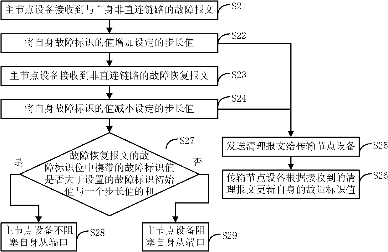
[0075] The Ethernet ring network link fault recovery method provided by the second embodiment of the present invention is improved on the basis of the first embodiment, specifically, in the first embodiment above, it is judged whether the updated fault identification value of the master node device itself is greater than the set The initial value of the fault identification is replaced by judging whether the link identification value carried in the received fault recovery message is greater than the sum of the set initial value of the fault identification and a set step value, and the master node determines whether it is blocked according to the judgment result from the port. The method flow is as follows image 3 As shown, the execution steps are as follows:

[0076] Step S21: The master node device receives a failure message of a link not directly connected to itself.

[0077] Specifically refer to the description of step S11. At this time, the fault identification bit of ...

Embodiment 3

[0099] The Ethernet ring network link failure recovery method provided by Embodiment 3 of the present invention specifically describes the processing flow for the failure of more than two links in the Ethernet ring network, wherein the initial value of the set fault identification is 0, and the step value is 1 Take this as an example. In this method, the reserved field of the EAPS message is used, specifically, the reserved field in the sent fault (link down), fault recovery (link up) and cleaning (flush) message is used to set the fault identification bit (Link state) to Identifies link failure conditions in the Ethernet ring network. The method flow is as follows Figure 4 As shown, the execution steps are as follows:

[0100] Step S31: The master node device receives the fault message.

[0101] The messages in this embodiment, including fault messages, fault recovery messages, and cleaning messages, are all in the EAPS protocol message format specified by the RFC, and th...


PUM


Abstract

The invention discloses an Ethernet ring network link failure recovery method, an Ethernet ring network and node equipment, wherein the method comprises the steps: increasing a self-failure identification value by a determined step value when main node equipment receives a failure message of a link which is not directly connected to the equipment; reducing the self-failure identification value bythe step value when the main node equipment receives a failure recovery message of the link which is not directly connected to the equipment, and judging whether the failure identification value which is reduced by the step value is greater than a determined failure identification initial value or not; if so, doing not block a self slave port; and otherwise blocking the self slave port. The problem of communication interruption caused by overlong recovery and convergence time of the Ethernet ring network is solved.

Description

technical field [0001] The invention relates to the technical field of communication, in particular to a recovery method for link faults of an Ethernet ring network, the Ethernet ring network and node equipment. Background technique [0002] Ethernet Automatic Protection Switching (Ethernet Automatic Protection Switching, EAPS) is a common ring protection technology applied in Ethernet ring topology, which belongs to the category of layer 2 link redundancy protection technology, and is the same as layer 2 link Compared with Spanning Tree Protocol (STP), which is a redundant protection technology, the biggest advantage is that the convergence time is at the level of 50 milliseconds, while the convergence time of STP is at the level of seconds. Therefore, EAPS technology is often deployed in the core network to improve link quality. Layer 2 convergence time on failure. [0003] RFC3619 proposed by IEFT defines the Ethernet ring network described in the technical core of EAPS ...

Claims


Application Information

Patent Timeline
Patent Type & Authority Patents(China)
IPC IPC(8): H04L12/437H04L12/70H04L12/24
Inventor 吴博文
Owner RUIJIE NETWORKS CO LTD
Why Eureka
Try Eureka