Supercharge Your Innovation With Domain-Expert AI Agents!

Annealing furnace of float glass manufacturing device

A technology of float glass and manufacturing equipment, which is applied in the direction of glass production, etc., can solve problems such as uneven cooling, difficulty in fully cooling, and lower quality of float glass, and achieve high-quality results

Inactive Publication Date: 2011-06-29
ASAHI GLASS CO LTD
View PDF4 Cites 15 Cited by
  • Summary
  • Abstract
  • Description
  • Claims
  • Application Information

AI Technical Summary

Problems solved by technology

[0008] In addition, since the float glass is naturally cooled in an open annealing furnace, it may be difficult to cool it sufficiently depending on the temperature of the gas environment and the type of glass.
In order to eliminate this lack of cooling, if partial air is blown in for cooling, it will cause uneven cooling and warp, which will reduce the quality of the float glass

Method used


Image

  • Annealing furnace of float glass manufacturing device
  • Annealing furnace of float glass manufacturing device
  • Annealing furnace of float glass manufacturing device

Examples


Embodiment Construction

[0041] Hereinafter, embodiments of the present invention will be described with reference to the drawings.

[0042] In addition, in this invention, the bottom of a glass ribbon means the direction in which a glass ribbon contacts a conveyance roll, and the top of a glass ribbon means the direction opposite to the said bottom.

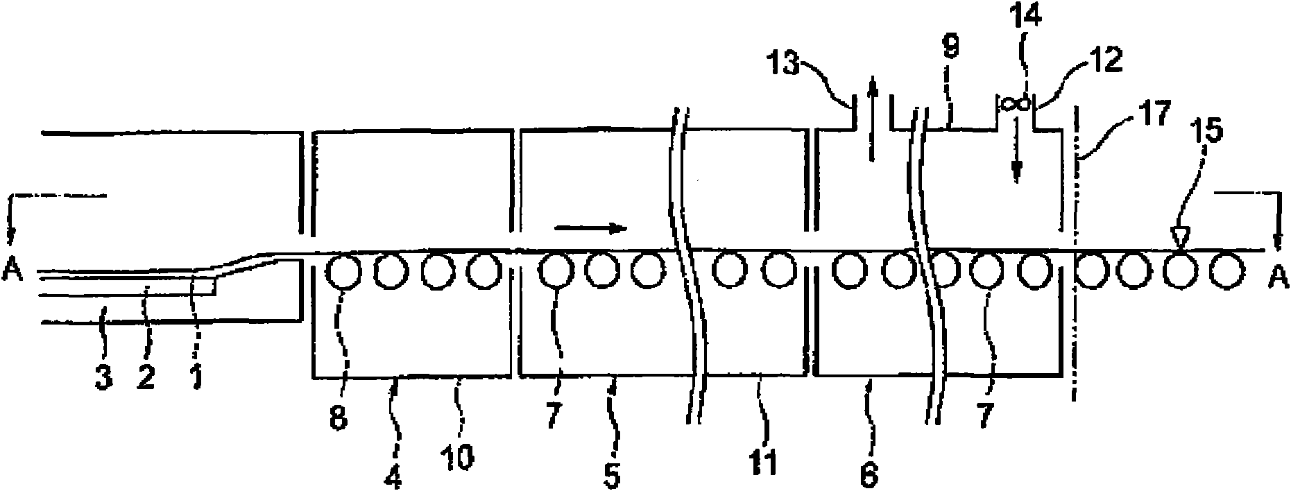
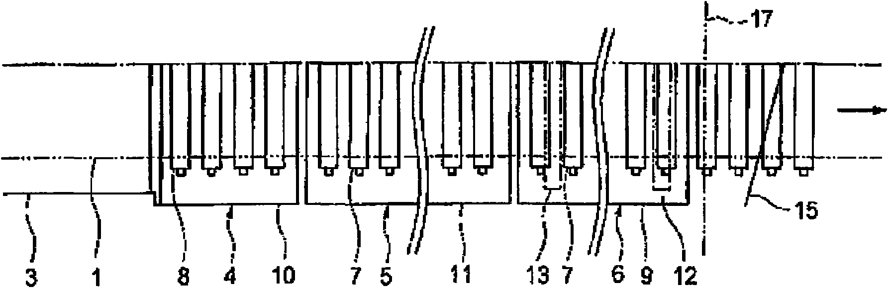
[0043] figure 1 It is a cross-sectional explanatory view of a slow cooling / annealing furnace according to a preferred embodiment of the present invention. figure 2 It is the plan view of its A-A part (only half of the figure is shown). exist figure 2 Only one half of the slow cooling / annealing furnace is shown in the figure, and the other half which is not shown is symmetrical and identical to it. As shown in the figure, a strip-shaped float glass 1 is formed on the molten tin 2 of the float kiln 3, and the lifting roller 8 provided by the lifting part 4 at the outlet of the float kiln 3 is pulled up from the molten tin 2 , and transported to the...


PUM


Abstract

The invention relates to an annealing furnace of a float glass manufacturing device, which is disposed at the downstream side of a slow-cooling furnace used to slowly cool the formed float glass, is transported by a transporting roller to the float glass slowly cooled by the slow-cooling furnace, and cools the float glass to a temperature at which the glass is capable to be cut off. Thereinto, the annealing furnace has a chamber surrounding the transporting roller, and the chamber is provided with a charging part for charging external air and an discharging part for discharging air in the chamber to the external; the pressure in the chamber is positive relative to the pressure outside the chamber.

Description

technical field [0001] The invention relates to an annealing furnace after slow cooling in the manufacture of float glass. Background technique [0002] Float glass, the molten glass produced in the field of molten glass manufacturing is supplied to the molten tin in the float kiln to form a ribbon glass, and after the formed ribbon glass is pulled out of the float kiln, it is cooled in a slow cooling furnace slow cooling to below the strain point temperature of the glass, and then cooled to the cutting temperature in the annealing furnace, and the float glass is cut into a specified size by a cutting device (refer to Patent Document 1 image 3 ). [0003] Figure 4 It schematically shows the process from manufacture to cutting of the float glass. Such as Figure 4 As shown, the float glass 41 formed in a ribbon shape on the molten tin 42 of the float kiln 43 is pulled up from the molten tin by the lifting roller 48 provided on the lifting part 44 at the exit of the float...

Claims


Application Information

Patent Timeline
IPC IPC(8): C03B25/00
CPCC03B18/20C03B25/08Y02P40/57
Inventor 中野胜之龙腰健太郎
Owner ASAHI GLASS CO LTD
Features
  • R&D
  • Intellectual Property
  • Life Sciences
  • Materials
  • Tech Scout
  • Unparalleled Data Quality
  • Higher Quality Content
  • 60% Fewer Hallucinations
Learn More