Magnetron sputtering target

A technology of magnetron sputtering and target head, which is applied in the field of magnetron sputtering targets, which can solve the problems of troublesome processing, single function, and inability to meet the direct sputtering function, etc., and achieves reduced processing costs, convenient space arrangement, and stable transmission Effect

Active Publication Date: 2011-06-29
SHENYANG SCI INSTR RES CENT CHINESE ACAD OF SCI
View PDF0 Cites 10 Cited by
  • Summary
  • Abstract
  • Description
  • Claims
  • Application Information

AI Technical Summary

Problems solved by technology

[0003] 1. The original co-sputtering scheme needs to process oblique holes on the large flange of the vacuum chamber, which is troublesome to process;
[0004] 2. Since the magnetron target is installed obliquely and the target head cannot be bent, the target head can neither adjust the bending angle nor sputter vertically upward. The magnetron target can only realize the co-sputtering function, and cannot meet the straight sputtering function. Relatively simple

Method used


Image

  • Magnetron sputtering target
  • Magnetron sputtering target
  • Magnetron sputtering target

Examples


Embodiment Construction

[0021] The present invention will be described in further detail below in conjunction with the accompanying drawings.

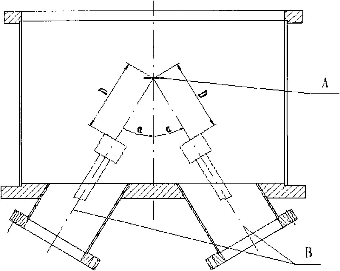
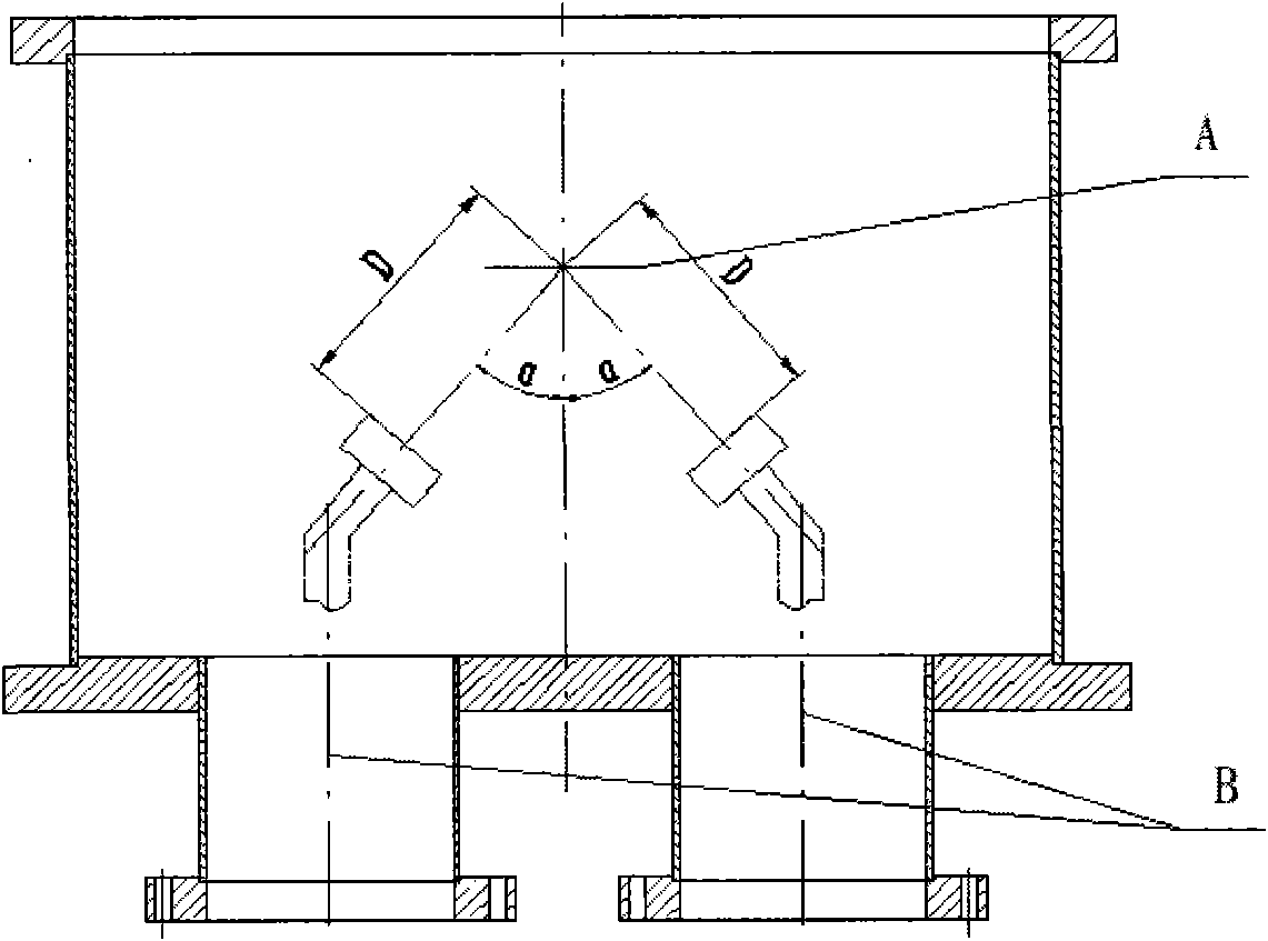
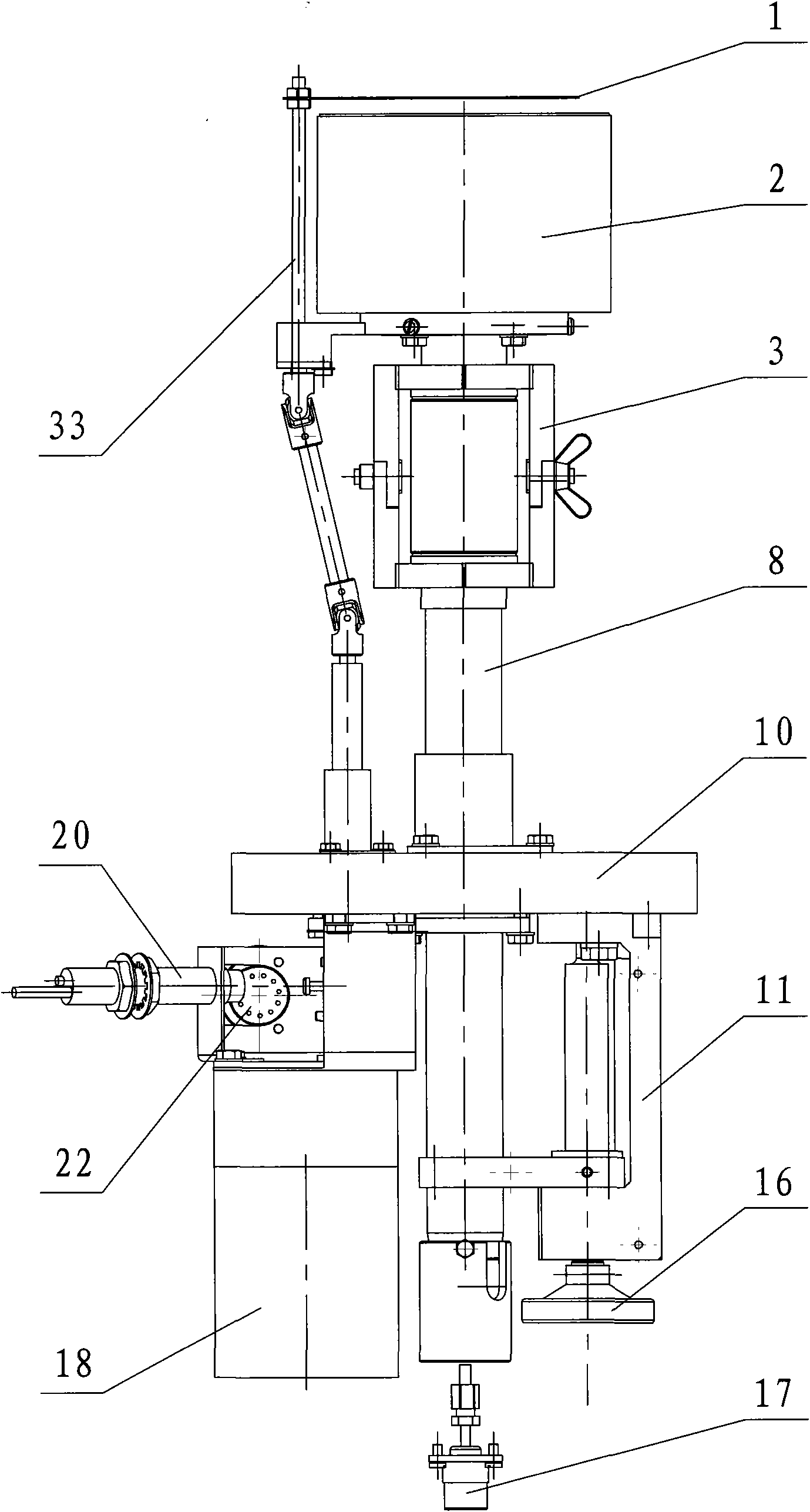
[0022] like Figure 3-5 As shown, the present invention includes a target head 2, a bending bellows assembly 3, a target support rod 8, a target support 10, a manual screw lifting assembly 11, a joint assembly 17, a driver 18 and a target baffle assembly 33, wherein the target support 10 is disc-shaped, on which the first and second guide seats 9, 25 are respectively arranged, and the target strut 8 can be reciprocally moved up and down and inserted on the first guide seat 9. One end of the target support rod 8 located above the target support 10 is connected to the target head 2 through a bent bellows assembly 3. The bent bellows assembly 3 includes a first nut 4, a bellows 7, and first and second bent plates 5, 6, the first and second bending plates 5, 6 can be a whole or composed of two parts with the same structure; when the first and second bending plat...


PUM


Abstract

The invention relates to coating equipment, in particular to a magnetron sputtering target, which comprises a target head, a bending corrugated pipe assembly, a target supporting rod, a target support, a manual spiral lifting assembly, a connector assembly, a driver and a target baffle assembly, wherein the target supporting rod is arranged on the target support in a vertical reciprocating way; one end of the target supporting rod positioned above the target support is connected with the target head through the bending corrugated pipe assembly; the target head can be bent relative to the target supporting rod through the bending corrugated pipe assembly; the target supporting rod positioned below the target support is connected with the manual spiral lifting assembly arranged on the target support; the driver is arranged on the target support, and the output end of the driver is connected with the target baffle assembly which can rotate relative to the target support and also can vertically reciprocate along the target supporting rod; and the other end of the target supporting rod positioned below the target support is provided with the connector assembly connected with a power supply. The target head is bent under the driving of the bending corrugated pipe assembly, so that a piece of magnetron equipment implements various coating processes, and the processing cost is reduced.

Description

technical field [0001] The invention relates to coating equipment, in particular to a magnetron sputtering target. Background technique [0002] At present, in the field of coating film preparation in China, it is often necessary to make alloy films of two, three or more materials, and the mechanical design needs to allow the target head to be tilted for co-sputtering. like figure 1 As shown in the figure, A is the position of the substrate, and the center line of the magnetron target is installed at the B position. The existing magnetron target is to make the flange connected to the magnetron target on the vacuum chamber and the nozzle tilt at an angle α, and the magnetron target is tilted Installation, the distance D between the target head and the position A of the substrate is a fixed value. However, the existing magnetron targets have the following disadvantages: [0003] 1. The original co-sputtering scheme needs to process oblique holes on the large flange of the v...

Claims


Application Information

Patent Timeline
Patent Type & Authority Applications(China)
IPC IPC(8): C23C14/35
Inventor 周颖刘丽华
Owner SHENYANG SCI INSTR RES CENT CHINESE ACAD OF SCI
Why Eureka
Try Eureka