Blade locking unit and blade clamping fixture
A blade and locking technology, applied in the direction of injection devices, manufacturing tools, used abrasive processing devices, etc., can solve the problems affecting the continuity and production efficiency of the product production process, affecting the normal processing of subsequent processes, and the failure of threads and elastic components and other problems, to achieve the effect of less parts, simple structure, fast and convenient clamping
- Summary
- Abstract
- Description
- Claims
- Application Information
AI Technical Summary
Problems solved by technology
Method used
Image
Examples
Embodiment 1
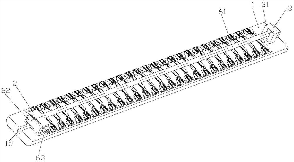
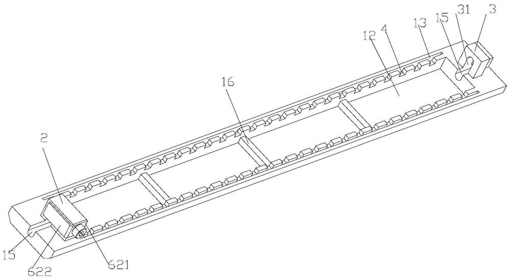
[0035] Such as Figure 1 to Figure 3 As shown, the blade locking unit of this embodiment includes a base 1 and a lock assembly. The two ends of the base 1 are provided with a first boss 2 and a second boss 3. The base 1 is connected to the first boss 2 and the second boss. A set of sipes is provided between the bosses 3, the set of sipes includes a plurality of slits 4 arranged at intervals along the length direction of the base 1, and a blade 5 is installed in each slit 4, and the lock assembly includes a pressing rod 61 and a shrapnel 62 , the first boss 2 is provided with a first installation hole 21, and the second boss 3 is provided with a second installation hole 31, and the shrapnel 62 is arranged on the first boss 2 and is located in the first installation hole 21 away from the second On one side of the mounting hole 31, one end of the pressure rod 61 (hereinafter referred to as the first end of the pressure rod 6) passes through the first mounting hole 21 and can push...
Embodiment 2
[0042] like Figure 4 and Figure 5 As shown, the blade locking unit of this embodiment includes a base 1 and a locking assembly. The two ends of the base 1 are provided with a first boss 2 and a second boss 3. The base 1 is connected to the first boss 2 and the second boss. A set of sipes is provided between the bosses 3, the set of sipes includes a plurality of slits 4 arranged at intervals along the length direction of the base 1, a blade 5 is installed in each slit 4, and the locking assembly includes pressing each blade 5 The pressure bar 61 in each sipe 4, the first boss 2 is provided with a first mounting hole 21 and a transition groove 22 communicating with the first mounting hole 21, and the second boss 3 is provided with a second mounting hole 31 One end of the pressure rod 61 (hereinafter referred to as the second end of the pressure rod 6) is installed in the second installation hole 31, and the other end (hereinafter referred to as the first end of the pressure r...
Embodiment 3
[0055] like Figure 6 and Figure 7 As shown, the blade clamping fixture of this embodiment includes a tray 7 and the blade locking unit in the above-mentioned embodiment 1. The tray 7 is a frame structure, and the two frames of the tray 7 along the length direction are provided with installation grooves 71 , There are multiple blade locking units, and the two ends of the base 1 of each blade locking unit are installed in the installation groove 71. The mounting groove 71 is an L-shaped groove.
[0056] The blade clamping fixture is connected with the sandblasting equipment, and the sandblasting process of the blade 5 can be realized, and the blades are clamped at one time, and the clamping is stable, thereby greatly improving the sandblasting efficiency and the production efficiency of the blades.
[0057] In this embodiment, the four corners of the tray 7 are provided with clamping holes 73 , and the frame of the tray 7 is provided with reinforcing ribs 72 .
PUM
 Abstract
Description
Claims
Application Information
 - R&D
- Intellectual Property
- Life Sciences
- Materials
- Tech Scout
- Unparalleled Data Quality
- Higher Quality Content
- 60% Fewer Hallucinations
Browse by: Latest US Patents, China's latest patents, Technical Efficacy Thesaurus, Application Domain, Technology Topic, Popular Technical Reports.
© 2025 PatSnap. All rights reserved.Legal|Privacy policy|Modern Slavery Act Transparency Statement|Sitemap|About US| Contact US: help@patsnap.com


