
Magnetron sputtering coating workpiece table

A magnetron sputtering coating and workpiece table technology, which is applied in sputtering coating, ion implantation coating, vacuum evaporation coating and other directions, can solve the problems of low production efficiency and low degree of automation, and achieves easy operation and improved adhesion. power, improve the degree of automation of equipment and the effect of production efficiency

Inactive Publication Date: 2015-12-02
48TH RES INST OF CHINA ELECTRONICS TECH GROUP CORP
View PDF3 Cites 2 Cited by
  • Summary
  • Abstract
  • Description
  • Claims
  • Application Information

AI Technical Summary

Problems solved by technology

Among the existing process equipment, for the workpiece table, there are deficiencies such as low degree of automation and low production efficiency.

Method used


Image

  • Magnetron sputtering coating workpiece table

Examples


Embodiment Construction

[0015] The present invention will be further described in detail below in conjunction with the accompanying drawings and specific embodiments.

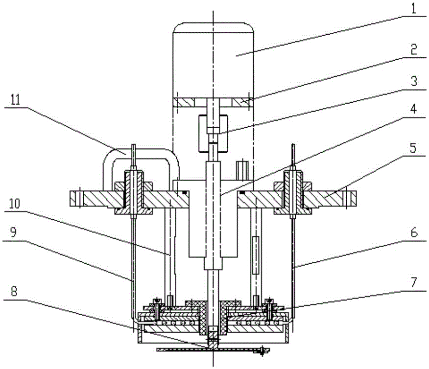
[0016] Such as figure 1 As shown, the magnetron sputtering coating workpiece table of the present invention includes a substrate table 8, a mounting flange 5, a heating body 9, a thermocouple 6 (such as a K-type thermocouple) and a speed regulating motor 1, and a substrate table 8 Used to install the substrate, the output end of the speed-regulating motor 1 is connected to the substrate table 8 through the coupling 3 and the magnetic fluid 4 and can rotate with the substrate table 8. By controlling the speed of the speed-regulating motor 1, the substrate can be The rotation speed of table 8 is adjusted. In this way, the substrate stage 8 can rotate and its speed can be adjusted (for example, the rotation speed adjustment range is 3-12rpm), thereby ensuring the uniformity of the sputtered metal film on the substrate, improving the ste...


PUM


Abstract

The invention discloses a magnetron sputtering coating workpiece table. The magnetron sputtering coating workpiece table comprises a substrate table, a mounting flange, a heating body, a thermocouple and a speed-adjustable motor, wherein the substrate table is used for mounting a substrate; the output end of the speed-adjustable is connected with the substrate table through a coupler and magnetic fluid and is capable of driving the substrate table to rotate; the mounting flange is mounted on a vacuum cavity; the heating body and the thermocouple are fixed to the mounting flange. The magnetron sputtering coating workpiece table has the advantages that the automation degree is high, the magnetron sputtering coating workpiece table rotates based on the substrate table, the speed and the temperature are controllable, and the film-coating uniformity and the adhesion of films can be improved.

Description

technical field [0001] The invention mainly relates to the field of semiconductor equipment, in particular to a magnetron sputtering coating workpiece table. Background technique [0002] As a very effective thin film deposition method, magnetron sputtering (MS) is widely and successfully used in many fields, especially in the fields of microelectronics, optical thin film and material surface treatment, for thin film deposition and surface coverage layer preparation. Compared with thermal evaporation and arc plating, the deposition process of MS technology is stable and easy to control. The target can be designed according to different needs, and it is easy to obtain a wide range of film uniformity. At the same time, the energy of MS film-forming ions is generally higher than that of thermal evaporation and lower than that of arc plating, so it is easy to obtain a film with good adhesion, high density and low internal stress. Among the existing process equipment, for the w...

Claims


Application Information

Patent Timeline
Patent Type & Authority Applications(China)
IPC IPC(8): C23C14/50C23C14/35
Inventor 陈庆广陈特超佘鹏程毛朝斌
Owner 48TH RES INST OF CHINA ELECTRONICS TECH GROUP CORP
Learn More