Centrifugal fan

A centrifugal fan and fan wheel technology, which is applied in cooling/ventilation/heating transformation, instrumentation, electrical digital data processing, etc., can solve the problem of centrifugal fan noise increase and achieve the effect of reducing rotation noise

Inactive Publication Date: 2011-06-29
FU ZHUN PRECISION IND SHENZHEN +1
View PDF4 Cites 9 Cited by
  • Summary
  • Abstract
  • Description
  • Claims
  • Application Information

AI Technical Summary

Problems solved by technology

The air volume and wind pressure of the centrifugal fan directly affect its heat dissipation efficiency. The greater the air volume and wind pressure of the centrifugal fan, the higher the heat dissipation efficiency. Generally, the higher the speed of the centrifugal fan, the greater the air volume and wind pressure. However, high RPM will also result in increased noise from the centrifugal fan

Method used


Image

  • Centrifugal fan
  • Centrifugal fan
  • Centrifugal fan

Examples


Embodiment Construction

[0013] The present invention will be further described below in conjunction with the embodiments with reference to the accompanying drawings.

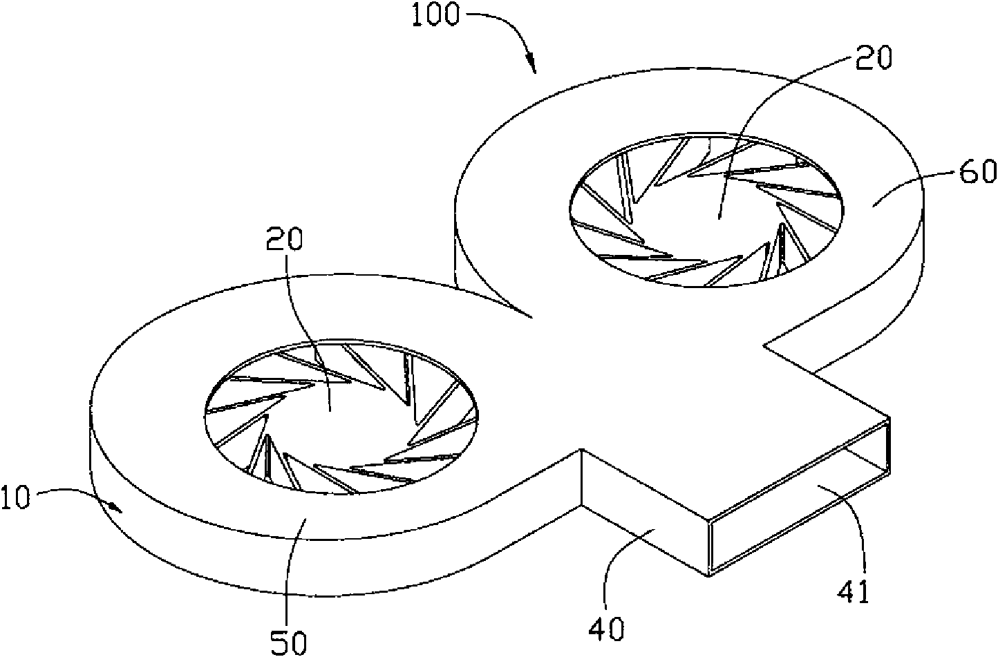
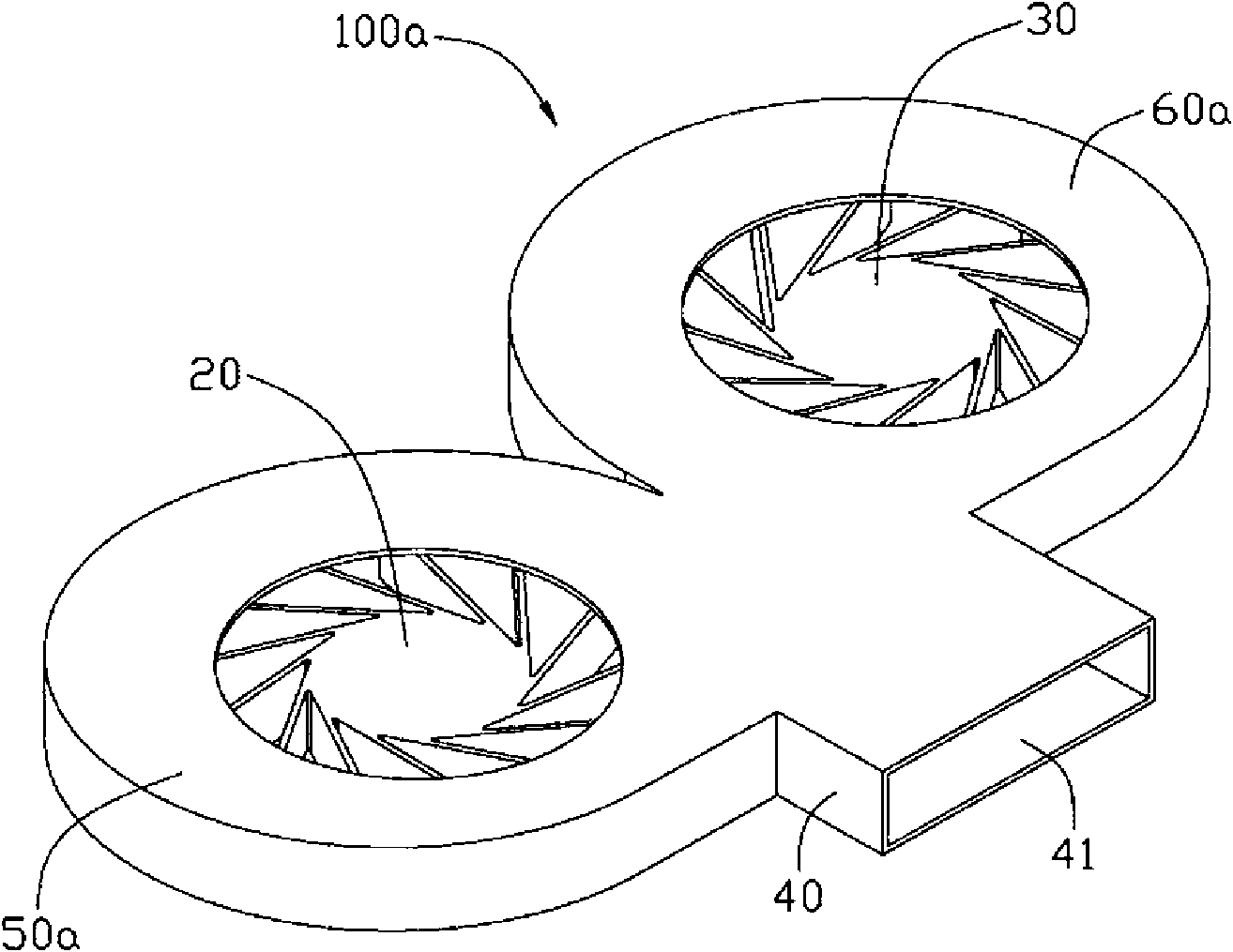
[0014] figure 1 and figure 2 Shown is a centrifugal fan 100 in a preferred embodiment of the present invention, the centrifugal fan 100 includes a hollow fan frame 10 and a first fan wheel 20 and a second fan wheel pivotally connected in parallel to the fan frame 10 30.

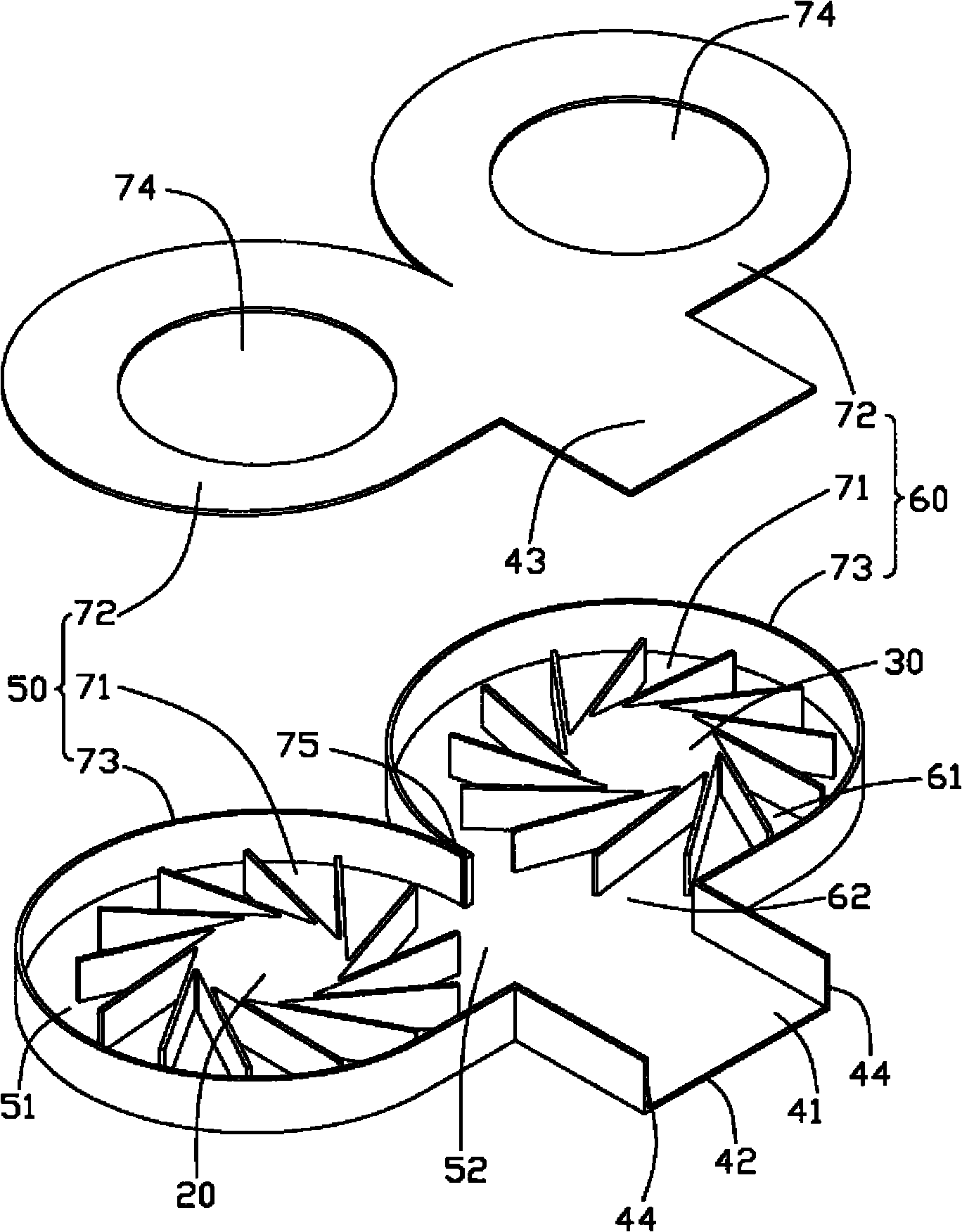
[0015] The fan frame 10 includes a confluence part 40 and a first frame body 50 and a second frame body 60 connected to the confluence part 40, and the first frame body 50 and the second frame body 60 are symmetrically arranged on the confluence part 40. On both sides of one end (the top end in this embodiment), an air outlet 41 is formed at the other end (the bottom end in this embodiment) of the confluence part 40 .

[0016] The confluence portion 40 includes a bottom plate 42 , a top plate 43 and two deflectors 44 . The two deflectors 44 are located on two side...


PUM


Abstract

The invention relates to a centrifugal fan which comprises a fan frame, wherein the fan frame comprises a convergence part, a first frame body and a second frame body which are connected with the convergence part; the first frame body and the second frame body are respectively arranged at two sides of one end of the convergence part; the other end of the convergence part forms an air outlet; a first containing space is formed in the first frame body; a second containing space is formed in the second frame body; a first fan wheel is arranged in the first containing space; a second fan wheel is arranged in the second containing space; the first frame body is provided with a first notch communicated with the convergence part; the second frame body is provided with a second notch communicated with the convergence part; and the air flow generated by the first fan wheel and the air flow generated by the second fan wheel are converged by the convergence part, and exhausted to the outer side of the centrifugal fan through the air outlet.

Description

technical field [0001] The invention relates to a centrifugal fan, in particular to a centrifugal fan used for cooling heat-generating electronic components. Background technique [0002] With the rapid development of the electronic information industry, the heating electronic components in electronic equipment, such as the CPU in the computer, are developing towards high speed, high function and miniaturization, which leads to the increasing heat generation and heat density of these heating electronic components. The larger the temperature, if the heat of these heating electronic components is not dissipated in time and effectively, the performance of these heating electronic components will be greatly affected, and their service life will also be shortened. Therefore, the heating electronic components in electronic equipment must be To dissipate heat. [0003] Currently, centrifugal fans are usually used in the industry to dissipate heat from electronic devices such as no...

Claims


Application Information

Patent Timeline
Patent Type & Authority Applications(China)
IPC IPC(8): F04D29/44F04D29/66F04D29/28H05K7/20G06F1/20
CPCF04D29/424F04D25/166G06F1/20
Inventor 查新祥余业飞郭哲豪
Owner FU ZHUN PRECISION IND SHENZHEN
Why Eureka
Try Eureka