Backlight module

A backlight module and optical coupling technology, applied in the field of backlight technology, can solve the problems of increasing the overall cost of the backlight module and assembly complexity, etc.

Inactive Publication Date: 2011-06-29
AU OPTRONICS CORP
View PDF6 Cites 6 Cited by
  • Summary
  • Abstract
  • Description
  • Claims
  • Application Information

AI Technical Summary

Problems solved by technology

[0004] However, the light mixing distance of the two direct-lit backlight modules mentioned above still needs to be 10-15mm
In addition, using an extra lens 130 will increase the overall cost and assembly complexity of the backlight module

Method used


Image

  • Backlight module
  • Backlight module
  • Backlight module

Examples


Embodiment Construction

[0032] In order to make the description of the present invention more detailed and complete, reference may be made to the attached drawings and various embodiments described below, and the same numbers in the drawings represent the same or similar elements. On the other hand, well-known elements and steps have not been described in the embodiments in order to avoid unnecessarily limiting the invention.

[0033] As used herein, "about," "approximately," or "approximately" is used to modify any quantity that may vary slightly, but which does not alter its essence. Unless otherwise specified in the embodiments, it means that the error range of the numerical value modified by "about", "approximately" or "approximately" is generally allowed within 20%, preferably within 10%. Within, and more preferably within five percent.

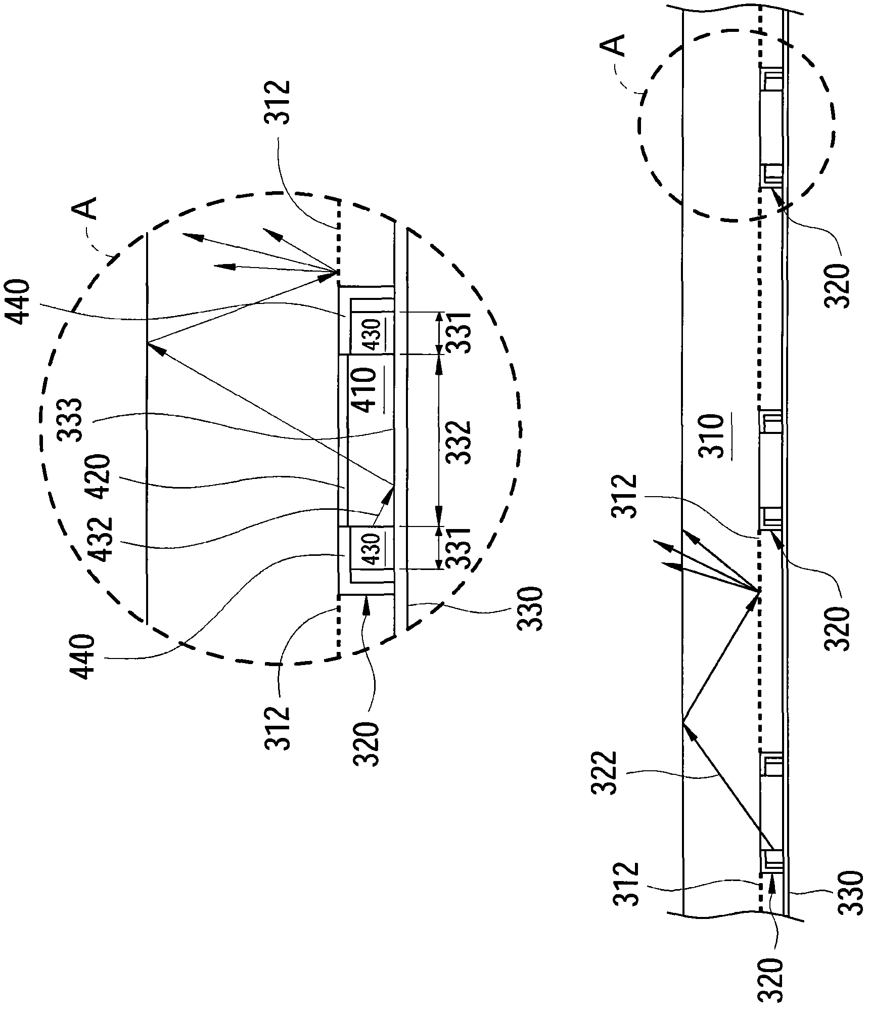
[0034] refer to image 3 , image 3 It is a sectional view and a partially enlarged view of a backlight module according to an embodiment of the present inv...


PUM


Abstract

The invention discloses a backlight module which comprises a light guide plate and multiple optical coupling units, wherein the optical coupling units are arranged below the light guide plate; each optical coupling unit comprises an optical coupling material, an optical cement and multiple light emitting components; the upper surface of the optical coupling material faces to the light guide plate; the optical cement is adhered between the upper surface of the optical coupling material and the light guide plate; and the light emitting components are arranged on the side of the optical coupling material. The backlight module disclosed by the invention can lead in the light rays emitted by the light emitting components with high efficiency by utilizing the optical coupling material and can lead the light out of the light guide plate through a scattering structure within a transfer distance so as to be beneficial to the expression of region control brightness.

Description

technical field [0001] The invention relates to a backlight technology, and in particular to a backlight module. Background technique [0002] With the rapid progress of liquid crystal display device manufacturing technology, and its advantages of lightness, lightness, power saving and no radiation, liquid crystal display devices are widely used in personal digital assistants, notebook computers, digital cameras, digital videography Machines, mobile phones, computer screens and LCD TVs and other electronic products. Coupled with the industry's active investment in research and development and the adoption of large-scale production equipment, the quality of liquid crystal display devices has been continuously improved, and the price has continued to decrease. Therefore, the application field of the liquid crystal display device is rapidly expanded. However, since the liquid crystal display panel in the liquid crystal display device is a non-self-illuminating display panel, ...

Claims


Application Information

Patent Timeline
Patent Type & Authority Applications(China)
IPC IPC(8): F21S8/00F21V8/00F21V17/00F21V19/00F21V5/00F21V7/00
Inventor 何振弘陈志光
Owner AU OPTRONICS CORP
Why Eureka
Try Eureka