
Sensor for testing characteristic of high-voltage switch

A high-voltage switch and sensor technology, applied in circuit breaker testing, instruments, measuring devices, etc., can solve problems such as inconsistent testing standards, cumbersome operations, and heavy workload

Inactive Publication Date: 2011-06-29
WUHAN SIWEI TECH INVESTMENT
View PDF0 Cites 0 Cited by
  • Summary
  • Abstract
  • Description
  • Claims
  • Application Information

AI Technical Summary

Problems solved by technology

[0003] In the field test, there are various high voltage levels, such as 10KV, 35KV, 110KV, 220KV and other voltage levels, as well as various types of high voltage switches, such as less oil, more oil, sulfur hexafluoride, vacuum, etc., with many styles and transmission methods Therefore, in the field test, it is necessary to configure the corresponding sensor holder to support the sampler according to the voltage level and type of the high-voltage switch to be tested. A unified and standardized sampler holder cannot be formed. In addition, the sampling ruler must be It is used in conjunction with the pull-out or push-in part of the sampler fixing seat, so that when the high-voltage switch operates, the sampling rod is driven to move and the sampling ruler is accurately pulled out or pushed into the fixing seat. There are technical problems in selecting the position of the sampler fixing seat and installing and fixing it; and With this kind of sensor, the on-site test needs to carry the sampler holder and support frame corresponding to the high-voltage switch. There is a defect that the sampler holder cannot be standardized, and the operation is cumbersome and the workload is heavy.

Method used


Image

  • Sensor for testing characteristic of high-voltage switch
  • Sensor for testing characteristic of high-voltage switch
  • Sensor for testing characteristic of high-voltage switch

Examples


specific Embodiment approach

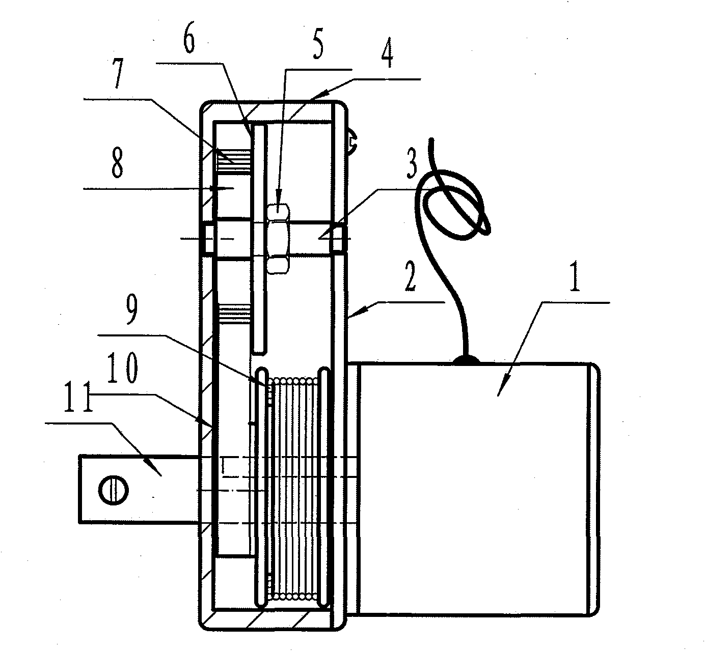
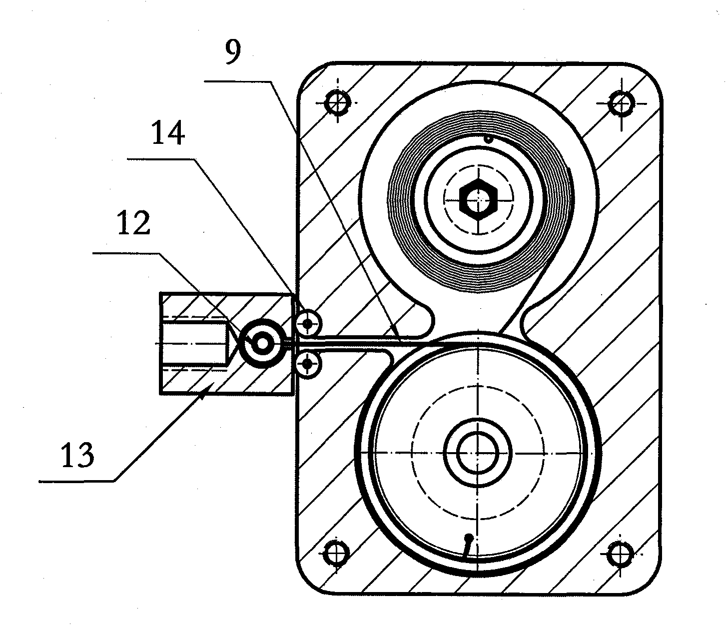
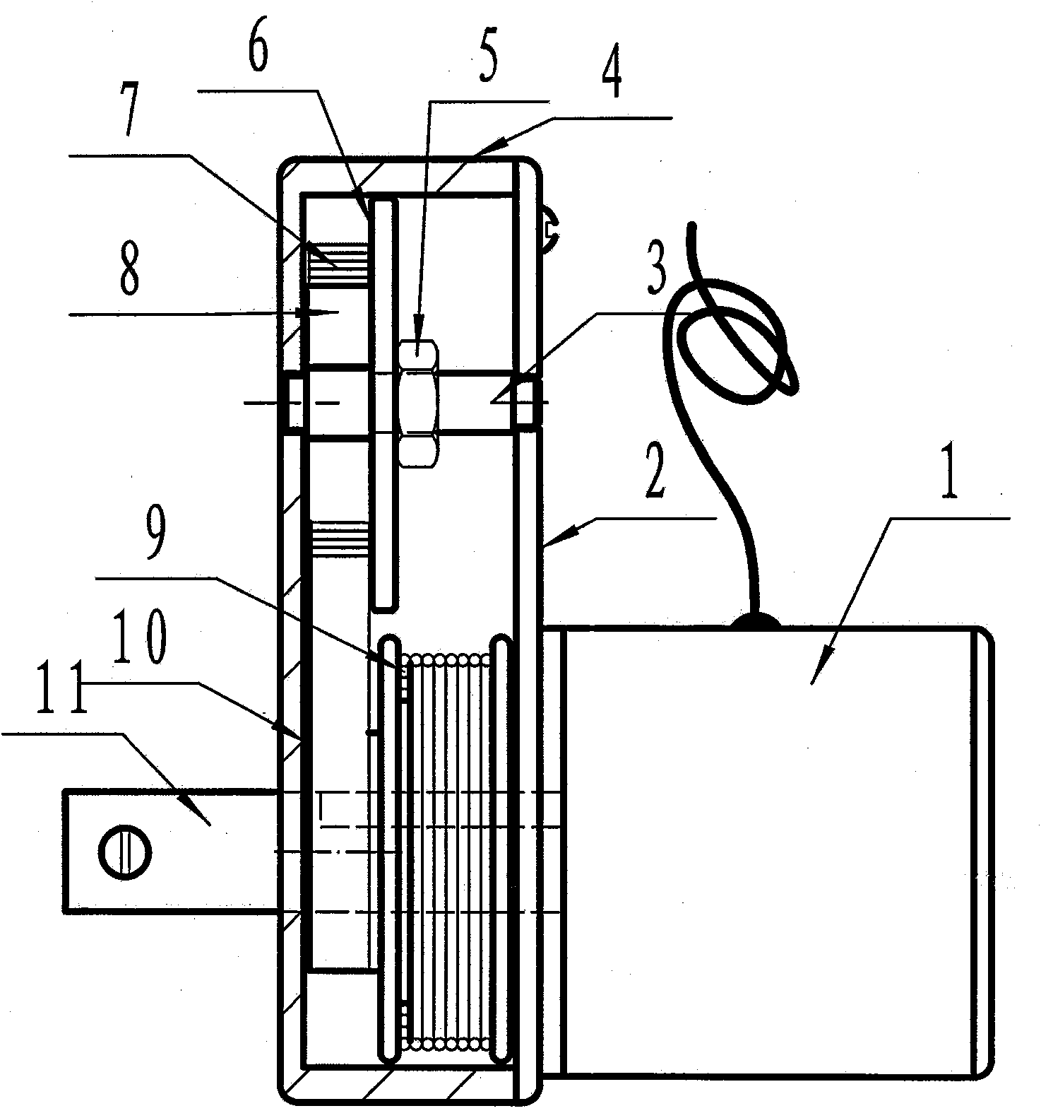
[0020] Such as figure 1 Shown is a schematic structural diagram of a specific embodiment of the sensor for high-voltage switch testing of the present invention, mainly consisting of a counter, a connector, and an energy storage mechanism. The energy storage mechanism includes a spring seat 8, a coil spring 7, a tape measure wheel 10, and a steel coil sheet 9 The coil spring 7 is installed on the spring seat 8, one end of the steel coil 9 is wound on the tape measure wheel 10, and the other end is wound on the coil spring 7, and the tape measure wheel 10 and the spring seat 8 are fixedly installed on the same plane;

[0021] The counter is composed of a grating, a light emitter, and a light receiver. The grating is in the shape of a disk, and the light emitter and the light receiver are located on both sides of the grating; in this embodiment, the finished encoder 1 is used for the counter. The encoder 1 is a rotary encoder, and the internal grating is disc-shaped, and there ar...


PUM


Abstract

The invention relates to a sensor for testing the characteristic of a high-voltage switch, which comprises a counter and a connecting piece and further comprises an energy storage mechanism; the energy storage mechanism mainly consists of a spring seat, a reed spring, a tapeline wheel and a steel coiling plate; the reed spring is arranged on the spare seat; one end of the steel coiling plate is wound on the tapeline wheel, and the other end of the steel coiling plate is wound on the reed spring; the tapeline wheel and the spring seat are fixedly arranged on the same plane; the counter consists of a grating, a light emitter and a light receiver, the grating is in a disc shape; the light emitter and the light receiver are positioned on both sides of the grating; one end of the connecting piece is fixedly connected with the energy storage mechanism and the counter; and the plate head of the steel coiling plate is wounded on the tapeline wheel is connected with a switch connecting piece. The sensor for testing the characteristic of the high-voltage switch has few components and simple structure, the switch connecting piece or shaft is connected with a movable contact according to the transmission manner of high-voltage switch when in test, and the sensor is convenient, flexible and quick to mount.

Description

technical field [0001] The invention relates to a displacement stroke measuring device, in particular to a switch test sensor, which is mainly used in a high-voltage switch action characteristic tester to collect moving contact stroke signals during high-voltage switch action. Background technique [0002] In the field of high-voltage switch action characteristic testing, the high-voltage switch action signal is collected by the sensor and transmitted to the test instrument. The sensor used in the industry consists of a sampling ruler, a sampler, and a sampler holder: the sampling ruler is embedded with a grating ruler, and the sampling ruler is connected to the moving contact of the high-voltage switch or to the moving contact through fasteners during the test The moving rod is connected; the sampler is equipped with light-emitting and receiving circuits, which are led out through cables; the sampler fixing seat is supported by a special bracket at the high-voltage switch t...

Claims


Application Information

Patent Timeline
IPC IPC(8): G01B11/02G01R31/327
Inventor 汪泓秦如学
Owner WUHAN SIWEI TECH INVESTMENT
Learn More