
Digital edge aligner for a PFD

A technology of frequency and phase detectors and aligners, which is applied to the automatic control of power and electrical components, and can solve problems such as precise alignment and difficult control of pulses

Active Publication Date: 2011-06-29
北京中科微投资管理有限责任公司
View PDF0 Cites 4 Cited by
  • Summary
  • Abstract
  • Description
  • Claims
  • Application Information

AI Technical Summary

Problems solved by technology

It is difficult to achieve precise alignment of the control pulse output from the existing frequency and phase detector to the control terminal of the charge pump

Method used


Image

  • Digital edge aligner for a PFD
  • Digital edge aligner for a PFD

Examples


Embodiment Construction

[0013] In order to make the objectives, technical solutions, and advantages of the present invention clearer, the embodiments of the present invention will be described in further detail below in conjunction with the accompanying drawings.

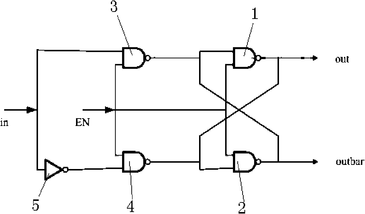
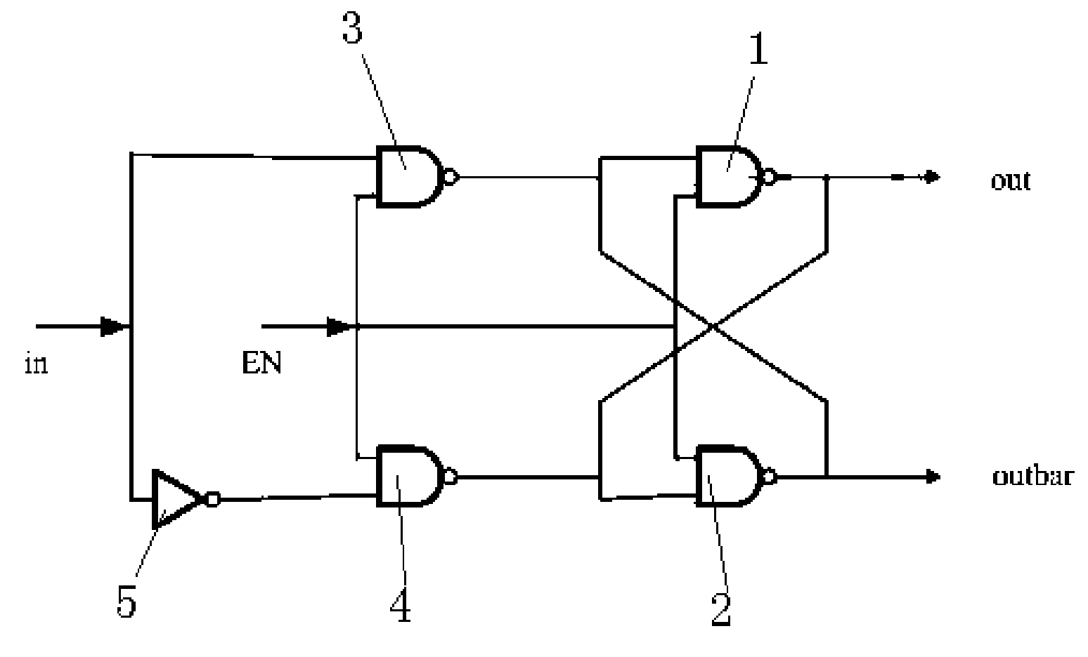
[0014] The present invention is a digital edge aligner for frequency phase detector. The digital edge aligner includes a flip-flop composed of basic logic gates, an inverter and a pair of NAND gates, which are connected to each other; It contains at least a pair of data input terminals, and can also include another control terminal. The flip-flop converts a signal into two pairs of inverted signals whose edges are aligned.

[0015] Such as figure 1 As shown, the pair of NAND gates is composed of 4 NAND gates, the 4 NAND gates are the first NAND gate 1, the second NAND gate 2, the third NAND gate 3, and the fourth NAND gate. Gate 4; the output terminal of the first NAND gate 1 is connected to the first input terminal of the second NAND gate 2,...


PUM


Abstract

The invention discloses a digital edge aligner for a PFD (Phase-Frequency Detector). The digital edge aligner comprises a trigger, a phase inverter, and a pair of NOT-AND gates, which are connected with one another, wherein the trigger is formed by a basic logic door and at least comprises a pair of data input terminals, and the trigger converts one path of signals into a two-path inversion signal pair for edge aligning. The digital edge aligner can be realized through a standard digital unit, and can ensure that control impulse output to the control terminal of a charge pump by the PFD is accurately aligned.

Description

Technical field [0001] The present invention relates to a frequency discriminator structure, in particular to a digital edge aligner for frequency discriminator. Background technique [0002] Phase-locked loop (phase-locked loop) is a closed-loop electronic circuit that can keep the frequency and phase of the controlled oscillator in a definite relationship with the input signal. It is a device that stabilizes the frequency in radio transmission, mainly including voltage-controlled oscillation It is composed of VCO and PLL IC. The voltage-controlled oscillator gives a signal, one part is the output, and the other part is compared with the local oscillator signal generated by the PLL IC through frequency division. In order to keep the frequency constant, a phase difference is required No change occurs. If there is a change in the phase difference, the voltage at the voltage output terminal of the PLL IC will change to control the VCO until the phase difference is restored to achie...

Claims


Application Information

Patent Timeline
Patent Type & Authority Applications(China)
IPC IPC(8): H03L7/085
Inventor 田欢欢张海英唐立田
Owner 北京中科微投资管理有限责任公司
Learn More