Eureka AIR delivers breakthrough ideas for toughest innovation challenges, trusted by R&D personnel around the world.

Method, system and device for allocating resources of uplink control channel of relay link

A technology for relay links and channel resources, which is applied in the field of allocation of uplink control channel resources of relay links, can solve problems such as non-consideration, and achieve the effect of resolving conflicts.

Active Publication Date: 2011-06-29
DATANG MOBILE COMM EQUIP CO LTD
View PDF3 Cites 14 Cited by
  • Summary
  • Abstract
  • Description
  • Claims
  • Application Information

AI Technical Summary

Problems solved by technology

[0004] In the prior art, only SPS (Semi-Persistent Scheduling, semi-persistent scheduling) and R-PUCCH (Relay-Physical Uplink Control Channel, Relay-Physical Uplink Control Channel, which is used to transmit ACK / NACK feedback corresponding to dynamically scheduled UEs) are considered. ) resource allocation, without considering how to allocate R-PUCCH resources for RN after the introduction of RN

Method used


Image

  • Method, system and device for allocating resources of uplink control channel of relay link
  • Method, system and device for allocating resources of uplink control channel of relay link
  • Method, system and device for allocating resources of uplink control channel of relay link

Examples


Embodiment 1

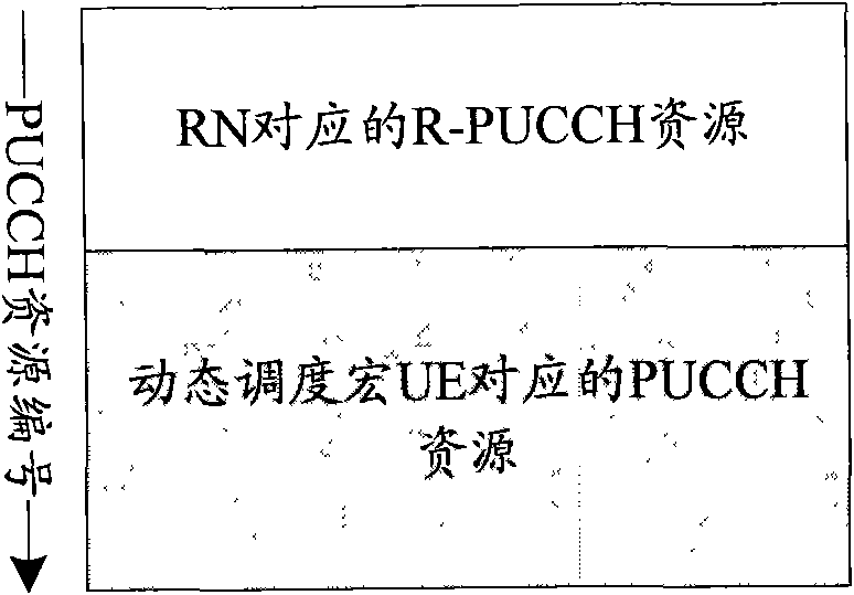
[0052] Such as image 3 As shown, it is a schematic diagram of PUCCH resource allocation according to an embodiment of the present invention. In this embodiment, the starting position of the R-PUCCH resource corresponding to the RN is smaller than the position of the PUCCH resource corresponding to the dynamically scheduled UE.

[0053] When the R-PUCCH resources are allocated to RNs in a common manner, the R-PUCCH resources corresponding to all RNs in the cell are multiplexed in the same resource region. The base station broadcasts the R-PUCCH resource area and the starting position of the PUCCH resource area to the RN and the dynamically scheduled macro UE respectively. The base station reserves the R-PUCCH resource area according to the maximum R-PUCCH resource required by all RNs in the cell. The base station reserves the R-PUCCH resource area according to the R-PUCCH The size of the resource area determines the starting position of the PUCCH resource area, ensuring that t...

Embodiment 2

[0060] Such as Figure 8 As shown, it is a schematic diagram of PUCCH resource allocation according to another embodiment of the present invention. The difference from the above embodiment is that the starting position of the R-PUCCH resource corresponding to the RN is greater than the position of scheduling the PUCCH resource corresponding to the UE.

[0061] The specific distribution method and analysis of this embodiment can be the same as that of Embodiment 1, and will not be described in detail here for the sake of simplicity.

[0062] Such as Figure 9 As shown, it is a structural diagram of a system for allocating relay link uplink control channel resources according to an embodiment of the present invention, and the system includes an eNB device 100 and an RN device 200 . The eNB device 100 is used to broadcast high-layer parameters to the RN device 200 or send R-PUCCH resource numbers to the RN device 200 through high-layer signaling, and receive uplink control infor...


PUM


Abstract

The invention provides a method and a system for allocating resources of an uplink control channel of a relay link. The method comprises the following steps that: a relay node (RN) receives a high-level parameter NPUCCHRN broadcast by an evolution Node B (eNB) or receives serial numbers of relay-physical uplink control channel (R-PUCCH) resources sent by the eNB through high-level signaling, wherein the high-level parameter NPUCCHRN is used for indicating the start position of regions, allocated by the RN, of the R-PUCCH resources; and the RN determines the corresponding R-PUCCH resources according to the high-level parameter NPUCCHRN or the serial numbers of the R-PUCCH resources and sends uplink control information by using the R-PUCCH resources. In the method and the system for allocating the resources of the relay uplink control channel, the allocation of the R-PUCCH resources to the RN is realized by broadcasting the high-level parameter to the RN or by sending the serial numbersof the R-PUCCH resources to the RN through the high-level signaling; and by the method and the system of the invention, the problem of collision between the R-PUCCH resources corresponding to the RN and physical uplink control channel (PUCCH) resources corresponding to dynamic scheduling macro user equipment (UE) also can be solved.

Description

technical field [0001] The present invention relates to the technical field of mobile communication, in particular to a method, system and device for allocating relay link uplink control channel resources. Background technique [0002] In the 3GPP Long Term Evolution-Advanced (LTE-A) system, a relay node (Relay Node, RN) cooperative transmission method is used to improve the service quality of cell edge users and expand cell coverage. [0003] Such as figure 1 Shown is a schematic structural diagram of the LTE-A system. After the introduction of RN, the nodes of the system include: Donor-eNB (evolved base station eNB with wireless connection with RN, referred to as DeNB), RN (entity existing between DeNB and UE), Relay-UE (data interaction with RN UE, referred to as R-UE) and macro UE (UE that directly exchanges data with DeNB). The interfaces include: Un interface (interface between RN and DeNB) and Uu interface (interface between UE and RN); wireless links include: back...

Claims


Application Information

Patent Timeline
Patent Type & Authority Applications(China)
IPC IPC(8): H04W48/10H04W72/04H04W88/08
Inventor 张文健潘学明沈祖康王立波
Owner DATANG MOBILE COMM EQUIP CO LTD
Why Eureka
Eureka Blog
Learn More