Light-emitting diode current balance circuit

A technology of light-emitting diodes and current balance, applied in the direction of electric light circuit layout, light source, electric light source, etc., can solve the problems of limited current and power loss, difficult to control, poor reliability of integrated circuits, etc., to achieve current balance, low cost, The effect of strong anti-disturbance characteristics of power supply voltage

Inactive Publication Date: 2011-06-29
TOP VICTORY INVESTMENTS
View PDF2 Cites 25 Cited by
  • Summary
  • Abstract
  • Description
  • Claims
  • Application Information

AI Technical Summary

Problems solved by technology

Although the integrated circuit can achieve more precise control and smaller circuit area, the reliability of the integrated circuit is not as good as that of the traditional circuit, and because the current and power loss that the integrated circuit can withstand is limited (genera

Method used


Image

  • Light-emitting diode current balance circuit
  • Light-emitting diode current balance circuit
  • Light-emitting diode current balance circuit

Examples


Example Embodiment

[0042] Example 1

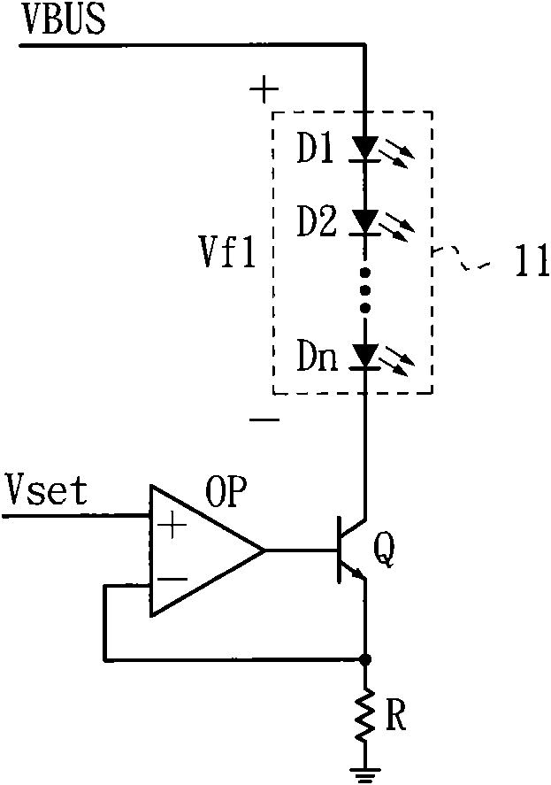
[0043] First of all, it should be noted that those skilled in the art know that a bipolar junction transistor (Bipolar Junction Transistor, BJT for short) has a first terminal (ie collector terminal), a second terminal (ie emitter terminal), and a control terminal (ie base terminal). , Field-Effect Transistor (FET) has a first terminal (that is, drain terminal), a second terminal (that is, source terminal), and a control terminal (that is, gate terminal). Both resistor and capacitor It has a first terminal and a second terminal. The diode, light emitting diode and Zener diode all have an anode terminal and a cathode terminal, which will not be described in detail below.

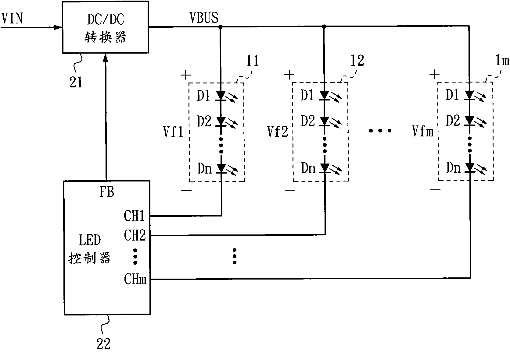
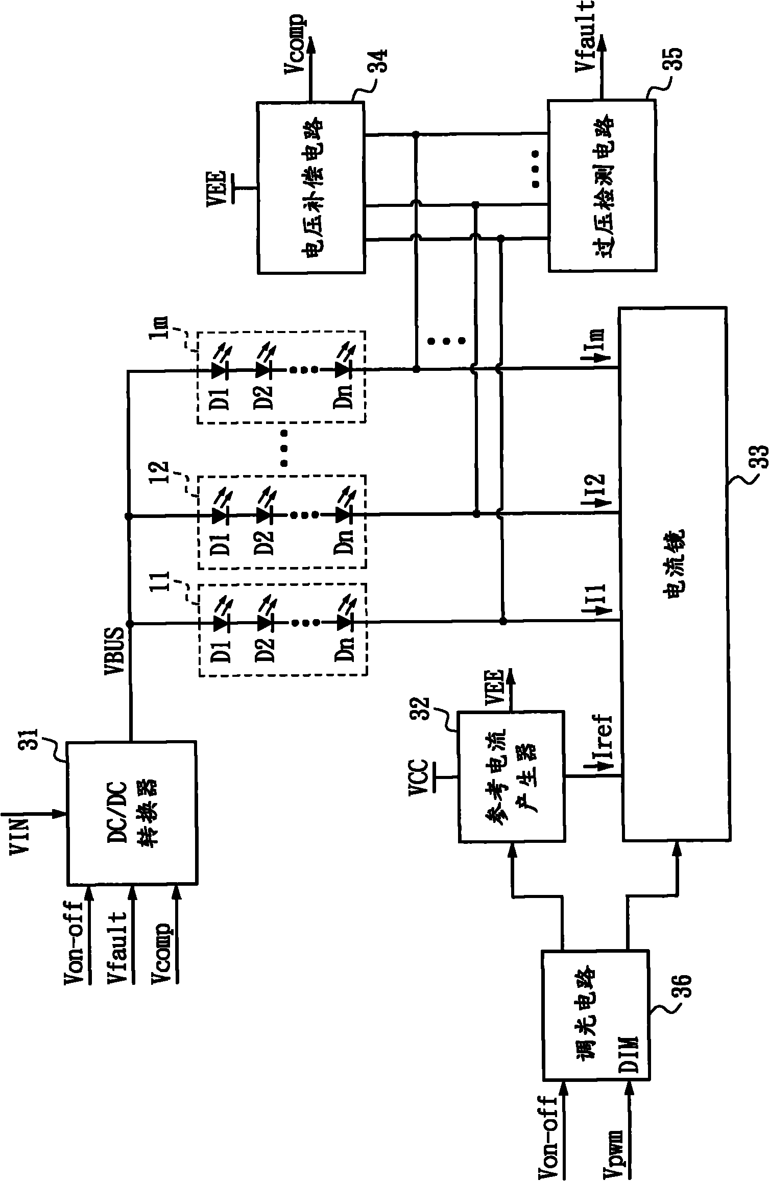
[0044] image 3 with Figure 4 These are respectively a block diagram and a circuit diagram of the LED current balance circuit provided by the embodiment of the present invention. See also image 3 with Figure 4 , The LED current balance circuit is used to drive multiple light strings 11 to 1m...


PUM


Abstract

The invention discloses a light-emitting diode current balance circuit, and belongs to the technical field of light-emitting diode driving. The light-emitting diode current balance circuit comprises a reference current generator, a current mirror and a voltage compensation circuit. The reference current generator provides reference current with a robust power voltage disturbance resistant characteristic for the current mirror to generate absorption current to each lamp string, and a framework used in the current mirror is not influenced by a transistor gain ratio, so the current mirror can stably control the current flowing through each lamp string. The voltage compensation circuit detects the voltage at end points of each lamp string so as to compensate forward conduction voltage drop. Lamp strings with different forward conduction voltage drops can be lightened, and the current flowing through the lamp strings is more balanced. In addition, a special light-emitting diode (LED) controller is not needed, and the light-emitting diode current balance circuit is low in cost and competitive.

Description

Technical field [0001] The invention relates to a light-emitting diode driving technology, in particular to a light-emitting diode current balance circuit. Background technique [0002] The ideal value of the forward conduction voltage drop of the LED (Light-Emitting Diode) indicated in the specification is 3.3V, but the actual forward conduction voltage drop after the LED is connected to the line will inevitably exist with the ideal value of 3.3V Error, if there is a 5% error, the actual forward voltage drop of the LED may range from 3.135V to 3.465V. Therefore, even if the light bar is formed by the same number and type of LEDs coupled in series, different forward voltage drops will still be generated on each light string. If the same light bar is applied to each light string For the light string voltage, each light string will have different currents flowing through each light string because of the actual forward voltage drop. Of course, the brightness provided by each light ...

Claims


Application Information

Patent Timeline
IPC IPC(8): H05B37/02
Inventor 林立韦李振强李吉欣黄元伯林文明
Owner TOP VICTORY INVESTMENTS
Why Eureka
Try Eureka