Heat transfer unit for internal combustion engine

A technology of heat transfer unit and internal combustion engine, which is applied in the direction of heat transfer modification, heat sink, heat exchanger, etc., and can solve problems such as adjustment and efficiency limitation of heat transfer equipment

Inactive Publication Date: 2011-06-29
PIERBURG GMBH & CO KG NEUSS
View PDF2 Cites 3 Cited by
  • Summary
  • Abstract
  • Description
  • Claims
  • Application Information

AI Technical Summary

Problems solved by technology

The efficiency of the heat transfer device of one of the embodiments described in this document is also limited due to the inability to adjust to the different temperature gradients that exist and the resulting different soot formation tendencies

Method used


Image

  • Heat transfer unit for internal combustion engine
  • Heat transfer unit for internal combustion engine

Examples


Embodiment Construction

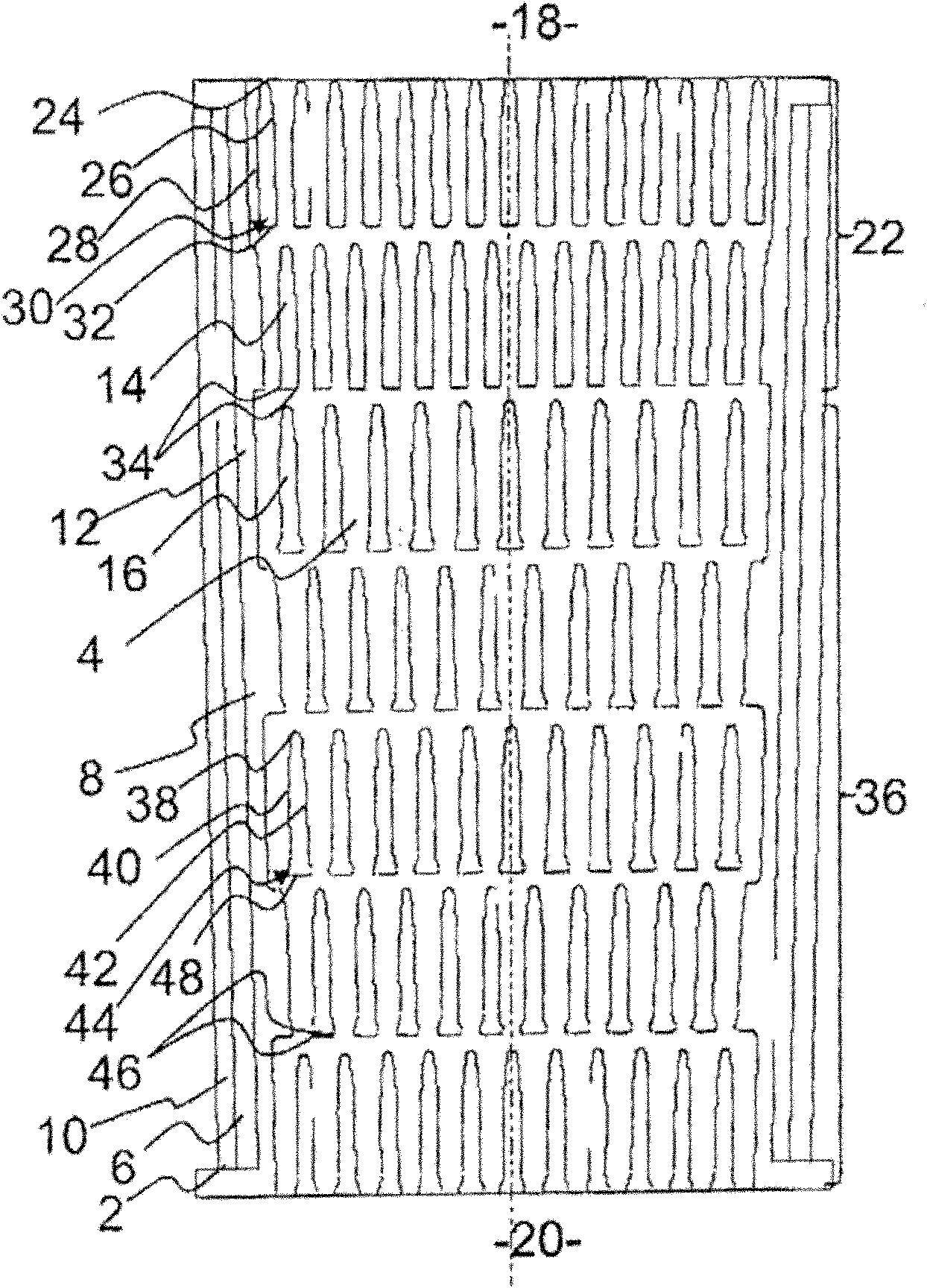
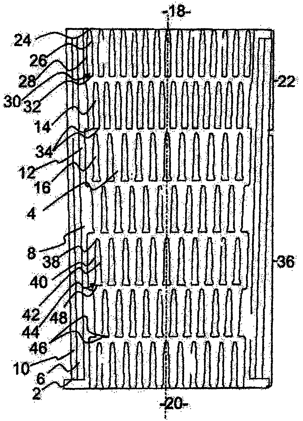
[0015] The heat transfer unit shown in the figure is formed by a housing 2, in which are provided passages 4 through which the fluid to be cooled flows and passages 6 through which the cooling fluid flows. Especially when using this heat transfer unit as an exhaust gas cooler, due to the forced soot into the exhaust gas, the problem of excessive soot formation may arise. For a clearer understanding, the channel 4 through which the fluid to be cooled flows is referred to below as The exhaust gas flows through the channels.

[0016] The housing 2 includes a multi-part inner housing 8 and an outer housing 10 surrounding the inner housing 8 and substantially spaced from the inner housing 8 .

[0017] In this embodiment, the channel 6 through which the coolant flows is arranged between the inner shell 8 and the outer shell 10, thus surrounding the channel 4 through which the fluid to be cooled flows, which is provided by the inner shell The peripheral wall of the body 8 is defined...


PUM


Abstract

The invention relates to heat transfer units comprising rib distances that vary across the running length for the purposes of increasing the cooling output. The heat transfer units often present problems due to sooting that is too high. The invention now provides that the channel (4), through which the fluid to be cooled flows, has two successive sections (22, 36) in the main flow direction, wherein the ribs (14, 16) have a constant cross-section in the discharge regions (30, 44) thereof in the first section (22), and cross-section expanding in the main flow direction in the second section (36). In this manner sooting is reduced in the rear region of the heat transfer unit while maintaining a continuous cooling output.

Description

technical field [0001] The invention relates to a heat transfer unit for an internal combustion engine, and more particularly to a heat transfer unit for cooling exhaust gases, comprising a channel through which a fluid to be cooled flows, the channel having an inlet and an outlet, the The unit also comprises channels through which the cooling fluid flows, at least one partition wall separating the channels through which the fluid to be cooled flows from the channel through which the cooling fluid flows, and from said partition wall along the main flow direction of the fluid to be cooled. Ribs extending into channels through which the fluid to be cooled flows. Background technique [0002] In general, heat transfer units for internal combustion engines are known and described in numerous patent applications. They are suitable both for cooling gases such as charge air or exhaust gases and for cooling liquids such as oil. [0003] It is known in particular that, depending on...

Claims


Application Information

Patent Timeline
Patent Type & Authority Applications(China)
IPC IPC(8): F28F13/08F28F19/00
CPCF28F19/00F28F2215/04F28F13/08F28D21/0003F28F2255/14
Inventor 汉斯-乌尔里克·库内尔迪特尔·杰利内克迈克尔·桑德斯迪特尔·索内森
Owner PIERBURG GMBH & CO KG NEUSS
Why Eureka
Try Eureka