Supercharge Your Innovation With Domain-Expert AI Agents!

Manipulator positioning mechanism for rotary filling machine

A positioning mechanism and manipulator technology, applied in the direction of manipulators, program control manipulators, manufacturing tools, etc., can solve the problems of high cost, complex structure, difficult installation and debugging, etc., and achieve the effect of low cost, simple and compact structure, and simple structure

Active Publication Date: 2012-10-03
TRUKING TECH LTD
View PDF0 Cites 0 Cited by
  • Summary
  • Abstract
  • Description
  • Claims
  • Application Information

AI Technical Summary

Problems solved by technology

However, the above-mentioned positioning method not only leads to complex structure, great difficulty in installation and debugging, but also high cost

Method used


Image

  • Manipulator positioning mechanism for rotary filling machine
  • Manipulator positioning mechanism for rotary filling machine
  • Manipulator positioning mechanism for rotary filling machine

Examples


Embodiment Construction

[0021] The present invention will be further described in detail below in conjunction with the accompanying drawings and specific embodiments.

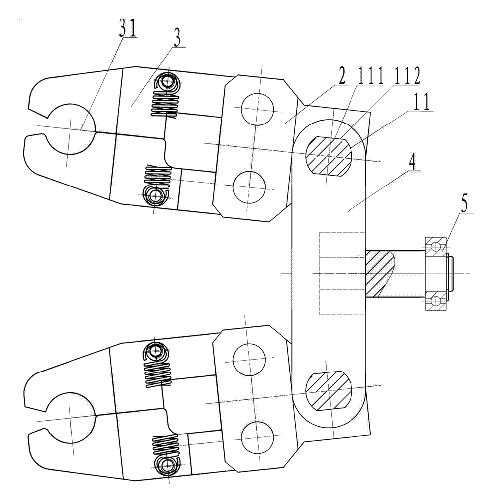
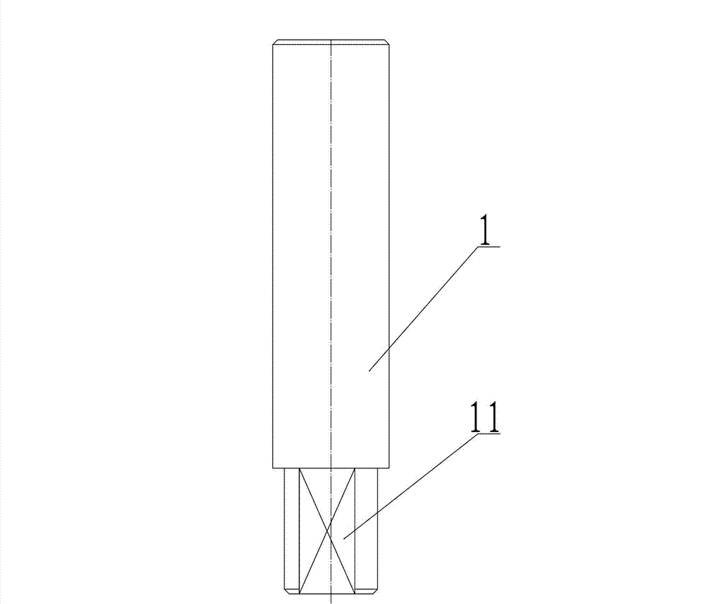
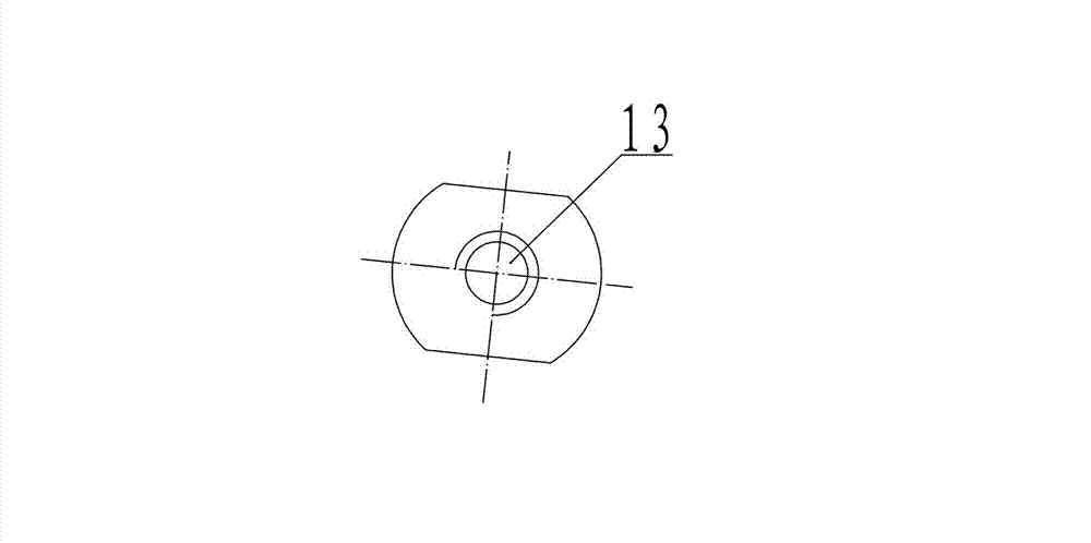
[0022] Such as figure 1 , figure 2 , image 3 , Figure 4 and Figure 5 As shown, the manipulator positioning mechanism used in the rotary filling machine of the present invention includes a guide part 11 formed on the manipulator lifting shaft 1 and a positioning hole 21 opened on the manipulator chuck seat 2 and cooperating with the guide part 11. The projection line 112 of at least one guide surface 111 on the part 11 in the horizontal direction is parallel to the clamping centerline 31 of the manipulator 3 . Through the above structure, the manipulator 3 can be positioned at any desired position in the circumferential direction, and the structure is simple and compact, and the cost is low; moreover, since the guide bearing 6 and the guide sleeve 7 do not need to be introduced, the installation and debugging are also convenie...


PUM


Abstract

The invention discloses a manipulator positioning mechanism for a rotary filling machine. The manipulator positioning mechanism comprises a guiding part which is formed on a manipulator hoisting shaft and a positioning hole which is arranged on a manipulator clamping base and matched with the guiding part, wherein a horizontal projection line of at least one guiding face of the guiding part is parallel to a holding central line of the manipulator. The manipulator positioning mechanism for a rotary filling machine has the advantages that the structure is simple and compact, the cost is low, the assembling and the debugging are convenient, the working is stable and reliable, and the like.

Description

technical field [0001] The invention mainly relates to the field of packaging machinery and equipment for medicine, food, etc., in particular to a rotary filling machine. Background technique [0002] Currently, rotary filling machines are widely used in food packaging and pharmaceutical machinery industries. see Figure 6 When working, the bottle body enters the manipulator 3 of the rotary filling machine after being handed over by the middle dial wheel, and is inserted into the bottle body through the filling head for synchronous tracking and filling. In order to position and install the manipulator 3 along the circumferential direction of the turntable, the existing method is generally to fix the manipulator 3 on a manipulator lifting shaft 1 through its manipulator chuck seat 2, and then limit the manipulator 3 through the guide bearing 6 located at the upper end of the manipulator lifting shaft 1. Positioning is performed in the guide groove 8 of the guide sleeve 7, th...

Claims


Application Information

Patent Timeline
Patent Type & Authority Patents(China)
IPC IPC(8): B25J9/10
Inventor 苏九洲龙煌辉刘和平刘振李鹏程唐岳
Owner TRUKING TECH LTD
Features
  • R&D
  • Intellectual Property
  • Life Sciences
  • Materials
  • Tech Scout
  • Unparalleled Data Quality
  • Higher Quality Content
  • 60% Fewer Hallucinations
Learn More