Humanized adaptive speed reducing system and design method thereof

A deceleration system and self-adaptive technology, applied in the field of transportation science, can solve the problem of not being able to adapt to changes in the speed environment in time, interference, etc., and achieve the effects of good economic benefits, convenient operation, and low engineering investment.

Inactive Publication Date: 2011-07-06
HARBIN INST OF TECH
View PDF4 Cites 21 Cited by
  • Summary
  • Abstract
  • Description
  • Claims
  • Application Information

AI Technical Summary

Problems solved by technology

The disadvantage of static deceleration belt design is that it cannot adapt to changes in the speed environment in time. Even when the vehicle is driving at a speed lower than the speed limit, it will still be disturbed by deceleration.

Method used


Image

  • Humanized adaptive speed reducing system and design method thereof
  • Humanized adaptive speed reducing system and design method thereof
  • Humanized adaptive speed reducing system and design method thereof

Examples


Embodiment 1

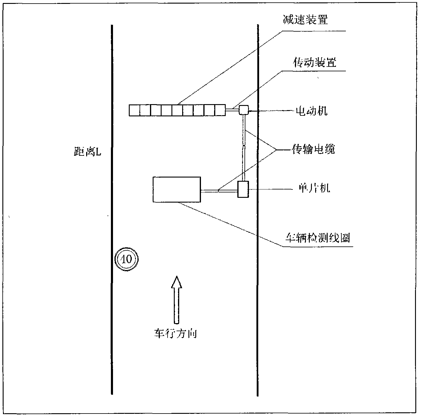
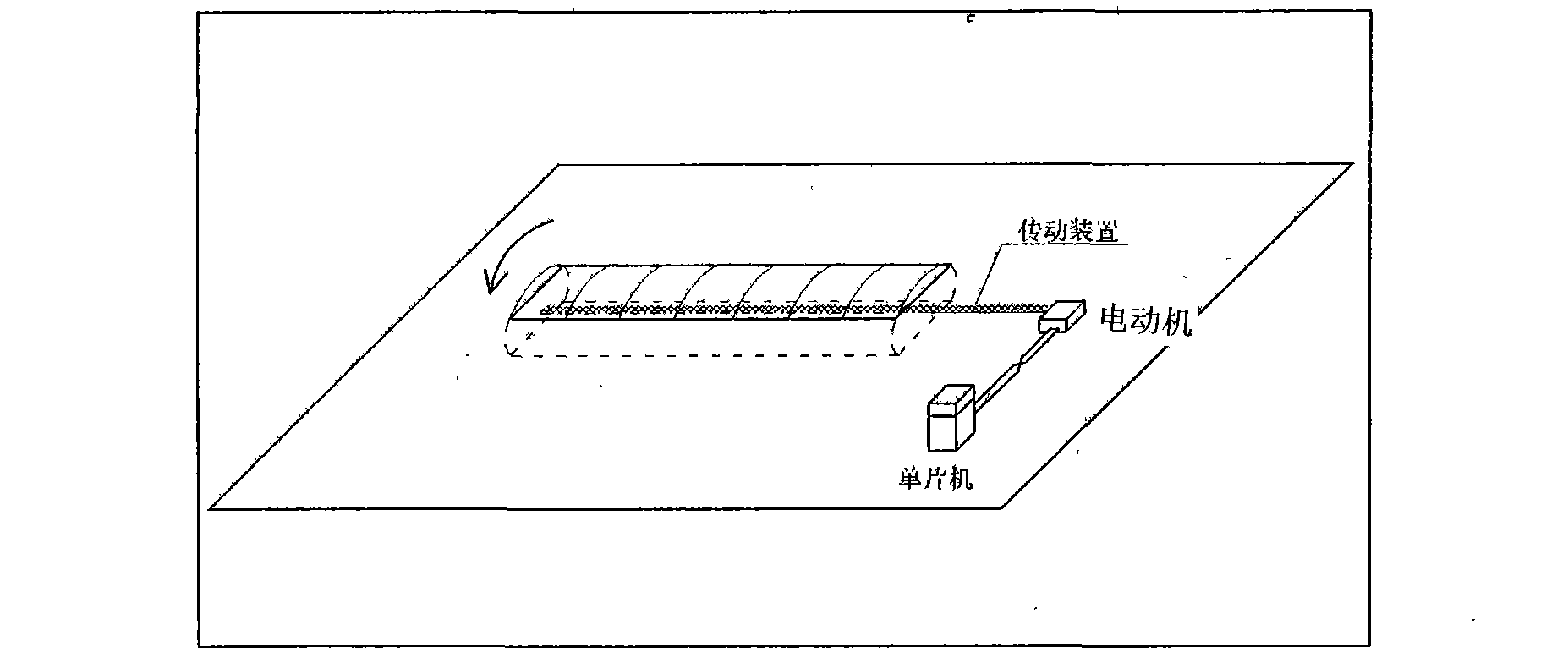
[0041] Example 1: Combining Figure 1-Figure 6 , a humanized self-adaptive deceleration system of the present invention, which is composed of a deceleration device, a transmission device, a motor, a transmission cable, a single-chip microcomputer and a vehicle detection coil. The microcontroller is connected, and the microcontroller is connected to the vehicle detection coil.

[0042] The design method of the described humanized adaptive deceleration system, the steps are as follows:

[0043] Step 1: Road section speed limit sign

[0044] Set the road section speed limit sign at a distance S in front of the vehicle detection coil to inform the driver to slow down. In order to enable the driver to slow down to a reasonable requirement within this distance, the distance S needs to meet certain requirements. The specific calculation is as follows:

[0045]

[0046] S——the distance between the vehicle detection coil and the speed limit sign, m;

[0047] V 1 ——Initial speed,...

Embodiment 2

[0068] Example 2: Combining Figure 1-Figure 6 , the design method of the humanized adaptive deceleration system of the present invention is to improve the efficiency and quality of the deceleration of the existing road deceleration belt, and give full play to the interactive relationship between the deceleration belt and the speed environment. The principle is simple, the construction difficulty is low and the speed is fast, which is conducive to popularization and application. A design method for a dynamic deceleration system.

[0069] The humanized self-adaptive deceleration system is mainly composed of pre-checking device, single-chip microcomputer, deceleration device, cable and other parts. The purpose of the present invention is achieved like this:

[0070] Assume that the speed limit of a certain road section is V 0 km / h, the humanized deceleration system is placed on this road section, the arc-shaped part of the deceleration device in the deceleration system protrud...

Embodiment 3

[0076] Example 3: Binding Figure 1-Figure 6 , the humanized adaptive deceleration system design method of the present invention comprises the following steps:

[0077] (1) Road section speed limit sign

[0078] Set the road section speed limit sign at the position S in front of the distance detection coil to inform the driver to slow down. In order for the driver to slow down to a reasonable requirement within this distance, the distance S needs to meet certain requirements. The specific calculation is as follows:

[0079]

[0080] S——the distance between the detection coil and the speed limit sign, m;

[0081] V 1 ——Initial speed, km / h;

[0082] V 0 ——Speed ​​limit value of road section, km / h;

[0083] - coefficient of friction;

[0084] f—coefficient of rolling resistance;

[0085] i——slope.

[0086] According to the average driving speed of the road section and the speed limit value of the road section, S is calculated. In the specific setting process, as lon...


PUM


Abstract

The invention provides a humanized adaptive speed reducing system and a design method thereof. The humanized adaptive speed reducing system judges whether to forcibly reduce the speed of an arrival vehicle or not by detecting the speed of the vehicle and comparing the speed with a road section speed limit value, and consists of a speed reducing device, a transmission device, an electric motor, a transmission cable, a singlechip and a vehicle detection coil, wherein the speed reducing device is connected with the transmission device; the transmission device is connected with the electric motor; the electric motor is connected with the singlechip through the transmission cable; and the singlechip is connected with the vehicle detection coil. The design method of the humanized adaptive speed reducing system comprises the following steps of: setting a section speed limit sign, arranging the speed reducing device, pre-checking the speed of a running vehicle, comparing the speed with the section speed limit value, transmitting a command, judging whether to reduce the speed and recover a speed reducing initial state or not, and the like. Only the running speed of the vehicle is needed to be measured and compared with a speed limit threshold value, so that whether the command is transmitted to the speed reducing device or not is judged, and the system is convenient to operate, has small construction investment, and can create good economic benefit.

Description

(1) Technical field [0001] The invention relates to traffic science, specifically a design method of a humanized self-adaptive deceleration system. (2) Background technology [0002] Speed ​​bumps, also known as speed bumps, are road safety facilities used to slow down the speed of motor vehicles and non-motor vehicles, and play an important role in suppressing the occurrence of traffic accidents. Speed ​​bumps usually work together with certain speed limit signs, which can not only ensure the safety of the car during driving, but also serve the purpose of buffering and decelerating to reduce traffic accidents. [0003] In recent years, with the development of our country's society and economy, the road grade has been continuously improved, the number of cars has increased rapidly, and traffic accidents on the road have become increasingly prominent. According to statistics in recent years, death caused by speeding accounts for about 15% of the total number of road traffic ...

Claims


Application Information

Patent Timeline
Patent Type & Authority Applications(China)
IPC IPC(8): E01F9/00E01F9/047G08G1/052E01F9/529
Inventor 裴玉龙蒋贤才沈瑞光韩娟赵蒙吴家明汤帅魏如峰慈玉生毛程远周侃漆巍巍王连震
Owner HARBIN INST OF TECH
Why Eureka
Try Eureka