Water receiving disc of dehumidifier

A technology for dehumidifiers and water trays, applied in the direction of preventing condensed water, etc., can solve the problems of increasing the cost of dehumidifier production materials, high overall cost of dehumidifiers, and weak fixed structures, achieving planning, saving production costs, The effect of saving development costs

Inactive Publication Date: 2011-07-06
LG ELECTRONICS (TIANJIN) APPLIANCES CO LTD
View PDF4 Cites 14 Cited by
  • Summary
  • Abstract
  • Description
  • Claims
  • Application Information

AI Technical Summary

Problems solved by technology

Since the water tray and the partition in the dehumidifier are only connected by screws on both sides, the force structure of the water tray completely depends on the two screws in the unsupported state. break
In addition, the chassis and the water tank are two separate parts. In order to ensure the overall support strength of the chassis to the dehumidifier, the chassis is made of metal. The chassis of sheet metal parts increases the production material cost of the dehumidifier, and the production of the chassis and water tank Two different sets of molds are required, so the cost of two molds is also required, resulting in a higher overall product cost for the dehumidifier

Method used


Image

  • Water receiving disc of dehumidifier
  • Water receiving disc of dehumidifier
  • Water receiving disc of dehumidifier

Examples


Embodiment Construction

[0027] The present invention is described in detail below with reference to accompanying drawing and embodiment:

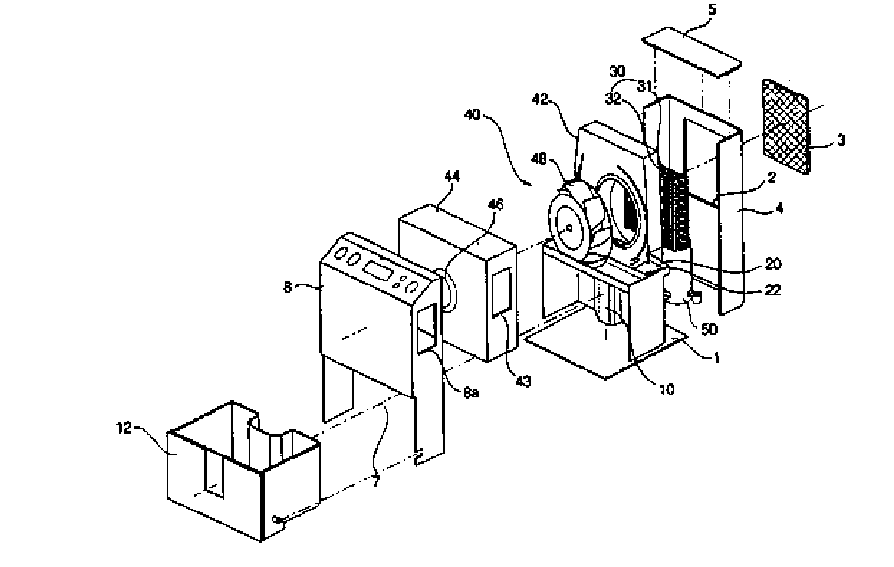
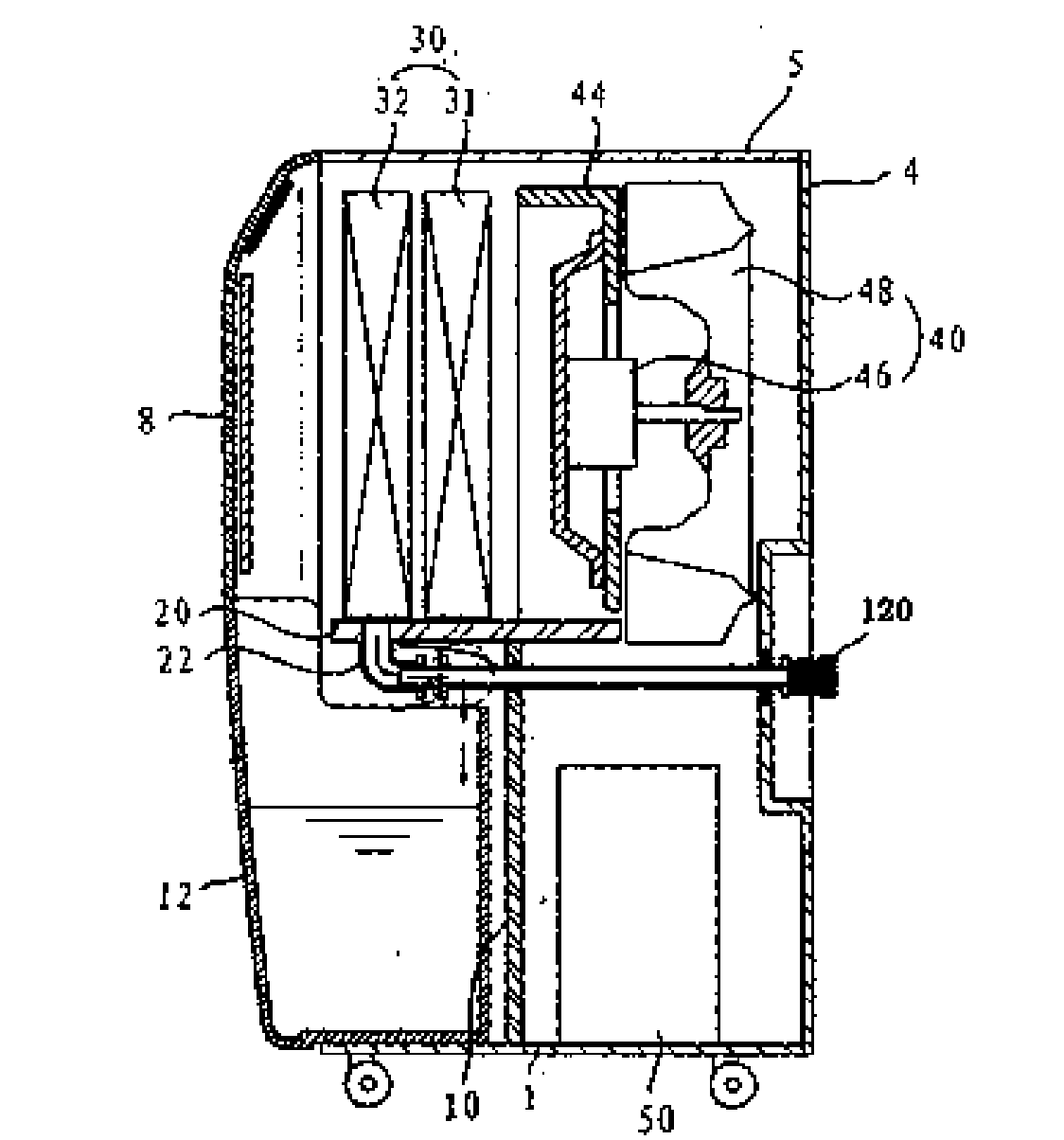
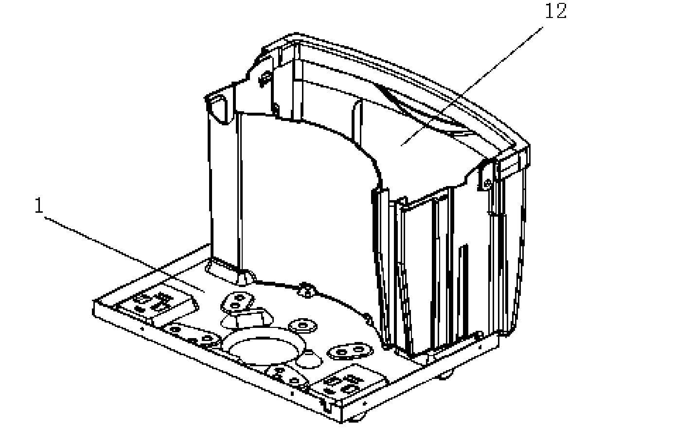
[0028] Figure 5 It is a schematic diagram of the decomposition structure of the dehumidifier in the present invention; Image 6 is a schematic diagram of the water tray of the dehumidifier of the present invention; Figure 7 It is a partial structural schematic diagram of the water receiving tray and the water tank of the dehumidifier of the present invention; Figure 8 It is a schematic diagram of the combination of the water tray and the water tank of the dehumidifier of the present invention.

[0029] Such as Figure 5 to Figure 8 As shown, in the water receiving tray of the dehumidifier of the present invention, the cabinet 4 forms the appearance of the dehumidifier, accommodates and protects various parts of the dehumidifier; The middle gasification absorbs heat, so the evaporator is in a low temperature state. When the inhaled humid air passes through t...


PUM


Abstract

The invention provides a water receiving disc of a dehumidifier. The dehumidifier comprises a machine box, an evaporator, a condenser, a water receiving disc, a fan, a water tank, a compressor and a control box, wherein the water tank and a chassis are in an integrally formed structure; the side wall of the water tank is formed by upwards extending the chassis; and the water receiving disc is fixed with the water tank and covers the water tank in a sealed manner. The water receiving disc is integrally formed by engineering plastic, is arranged at the upper part of the water tank, and covers the water tank in a sealed manner; condensed water is guided into the water tank through a water discharging opening; the integrally formed water receiving disc not only can completely bear and guide the condensed water flowing down from the evaporator, but also can play a role as a water tank cover which prevents the condensed water in the water tank from overflowing outwards; and the water tank cover does not need to be additionally assembled in the dehumidifier, so that the development cost of a mould is saved and the total production cost is reduced.

Description

technical field [0001] The invention belongs to the technical field of dehumidifiers, and specifically relates to a water tray of a dehumidifier whose chassis and water tank are integrally formed, closely connected with the water tank in the vertical direction, cover and seal the water tank, and prevent condensed water in the water tank from overflowing. Background technique [0002] Generally speaking, the dehumidifier introduces the humid air in the room into the inside of the chassis, reduces the humidity through a heat exchanger composed of an evaporator and a condenser with refrigerant flow, and then discharges the dehumidified air into the room to reduce the humidity. Device for indoor humidity purposes. [0003] figure 1 It is a schematic diagram of the decomposition structure of the prior art dehumidifier; figure 2 is a side sectional view of a prior art dehumidifier; image 3 It is a structural schematic diagram of a chassis and a water tank of a dehumidifier in...

Claims


Application Information

Patent Timeline
Patent Type & Authority Applications(China)
IPC IPC(8): F24F13/22
Inventor 刘学文鲍长桥
Owner LG ELECTRONICS (TIANJIN) APPLIANCES CO LTD
Why Eureka
Try Eureka