High-precision navigation method for landed or attached deep sky celestial body detector

A navigation method and detector technology, applied in the field of high-precision navigation, can solve the problems of inability to correct inertial navigation, navigation attitude, height and speed errors, and inability to meet high-precision landings, etc.

Active Publication Date: 2011-07-06
BEIJING INST OF CONTROL ENG
View PDF0 Cites 24 Cited by
  • Summary
  • Abstract
  • Description
  • Claims
  • Application Information

AI Technical Summary

Problems solved by technology

The current method is to use the inertial navigation position to determine the direction of the center of the celestial body, convert the distance obtained by the rangefinder from the detector to the surface of the celestial body into the height relative to the surface of the celestial body by using the inertial attitude, and combine it with the speed obtained by the speedometer to correct or replace it. The altitud

Method used


Image

  • High-precision navigation method for landed or attached deep sky celestial body detector
  • High-precision navigation method for landed or attached deep sky celestial body detector
  • High-precision navigation method for landed or attached deep sky celestial body detector

Examples


Embodiment Construction

[0043] The present invention will be described in further detail below in conjunction with the accompanying drawings and implementation.

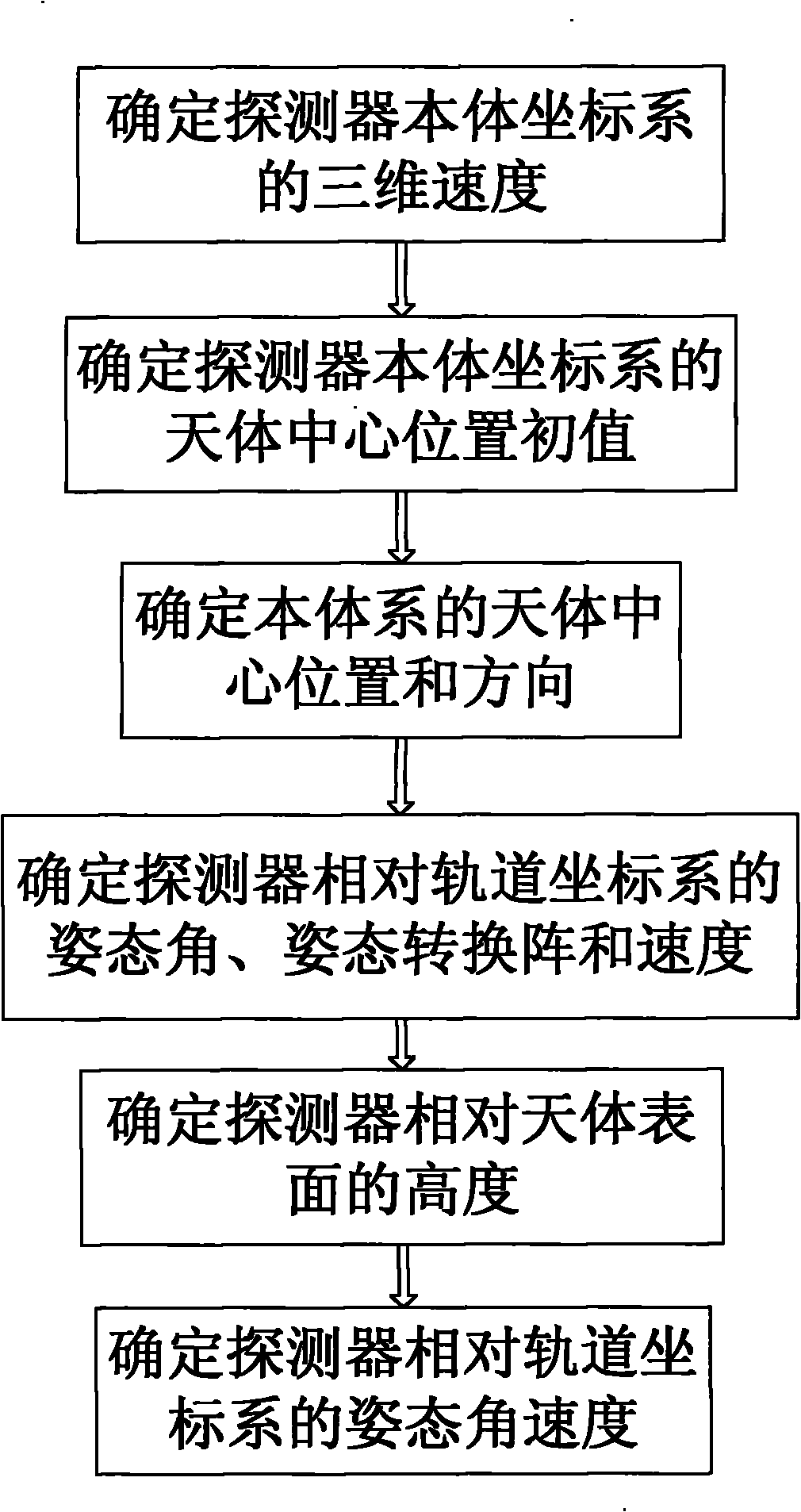
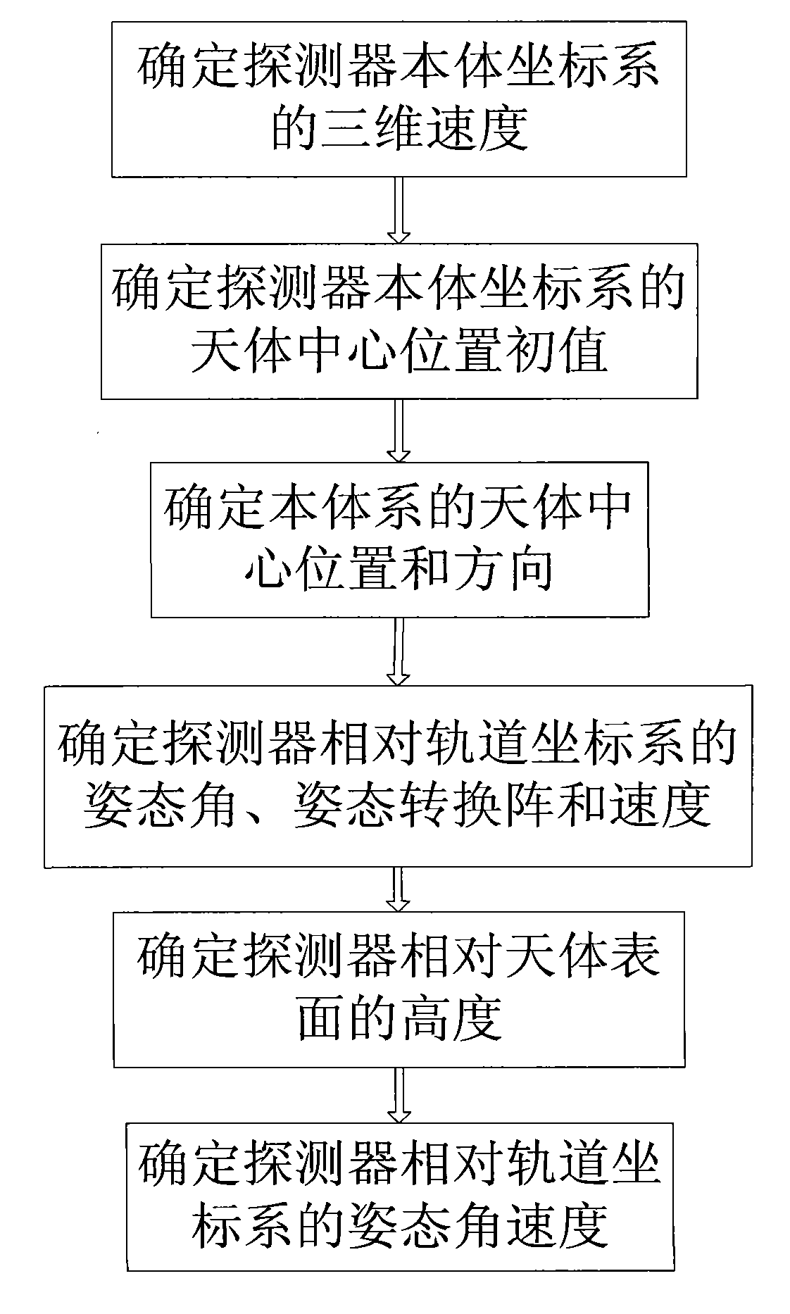
[0044] Such as figure 1 As shown, a high-precision navigation method for landing or attaching a deep-space celestial probe, it includes the following steps:

[0045] (1) Determine the three-dimensional velocity v of the detector body coordinate system b

[0046] Measure the velocity v of the three non-coplanar beams using the velocimeter on the detector 1 , v 2 , v 3 And the three beams of the speedometer are installed to point to l b1 , l b2 , l b3 , to determine the three-dimensional velocity of the detector body coordinate system

[0047] The body coordinate system is defined as: the origin is the center of mass of the detector, and the three axes point to the coordinate system of the main axis of inertia of the detector.

[0048] (2) Determine the initial value of the center position of the celestial body in the detector body...


PUM


Abstract

The invention belongs to the technical field of guidance, navigation and control of deep sky detectors, and particularly discloses a high-precision navigation method for a landed or attached deep sky celestial body detector. The method comprises the following steps: (1) determining the three-dimensional speed of a coordinate system of a detector body; (2) determining initial value of the center position of a celestial body in the coordinate system of the detector body; (3) determining the position and the direction of the celestial body in the body system; (4) determining the attitude angle and the speed of the detector relative to the coordinate system of an orbit; (5) determining the height of the detector relative to the surface of the celestial body; and (6) determining the angular speed of the detector relative to the coordinate system of the orbit. The method is not affected by the situation that inertial navigation error is constantly increased along the time, thereby effectively improving the precision of key navigation parameters for autonomous navigation of the landed or attached detector, and meeting the demands on navigation and control of the high-precision landed or attached deep sky celestial body detector.

Description

technical field [0001] The invention belongs to the technical field of guidance, navigation and control of deep space probes, and in particular relates to a high-precision navigation method that can be applied to landing or attaching deep space celestial body probes. Background technique [0002] Due to the long distance between deep space celestial bodies and the earth, it is difficult for ground-based deep space network navigation to meet the real-time and precision requirements of deep space landing or attached GNC system for detector status. Therefore, autonomous navigation has become a safe and accurate method. A key technology for landing or attaching to deep space objects. IMU-based navigation has been applied in landing missions such as Apollo and Surveyor in the United States and the Luna series in the former Soviet Union. Some recent deep-space landers, such as the Phoenix and MSL Mars landers of the United States, and the Selene-B lunar lander of Japan, still use...

Claims


Application Information

Patent Timeline
IPC IPC(8): G01C21/18
Inventor 黄翔宇王大轶
Owner BEIJING INST OF CONTROL ENG
Why Eureka
Try Eureka